Rotating shaft locking assembly, speed reducer and new energy automobile

A shaft and component technology, applied in the field of shaft end locking, can solve problems such as easy loosening of nuts, reduced reliability of self-locking, failure, etc., achieve the effect of stable shaft end locking and reliable operation of the shaft

Pending Publication Date: 2021-12-28
阿姆特上海新能源科技有限公司
View PDF6 Cites 0 Cited by
  • Summary
  • Abstract
  • Description
  • Claims
  • Application Information

AI Technical Summary

Problems solved by technology

[0004] In the output shaft locking scheme of the existing transmission and reducer, the output flange is first assembled on the output shaft, and then the nut is screwed into the output shaft, the nut is pressed against the end face of the flange, and then the tightening torque is applied to the nut. The nut is affected by the pre-tightening force, and a self-locking friction force is generated between the nut and the thread on the output shaft to achieve the purpose of axially limiting the output shaft. However, under the condition of alternating load, this self-locking The reliability will be reduced, so the nut is easy to loosen, resulting in unexpected displacement of the output shaft and failure

Method used


Image

  • Rotating shaft locking assembly, speed reducer and new energy automobile
  • Rotating shaft locking assembly, speed reducer and new energy automobile
  • Rotating shaft locking assembly, speed reducer and new energy automobile

Examples


Embodiment Construction

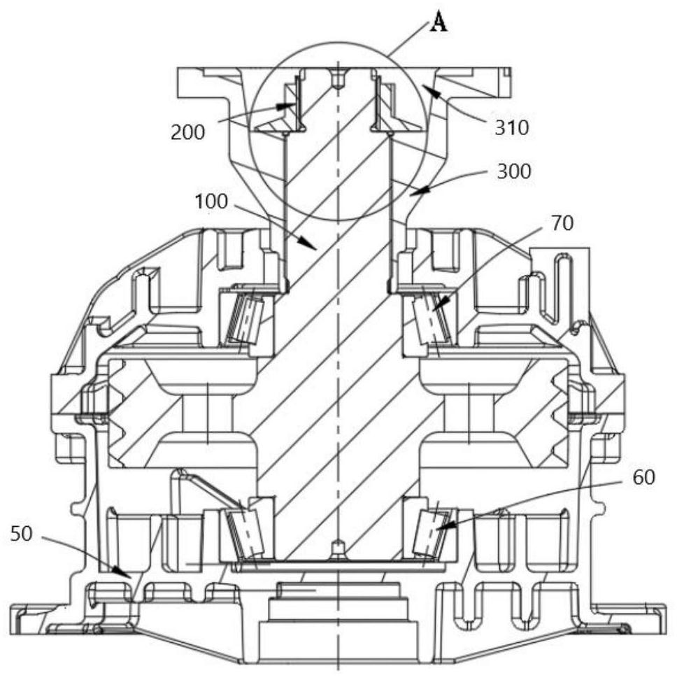
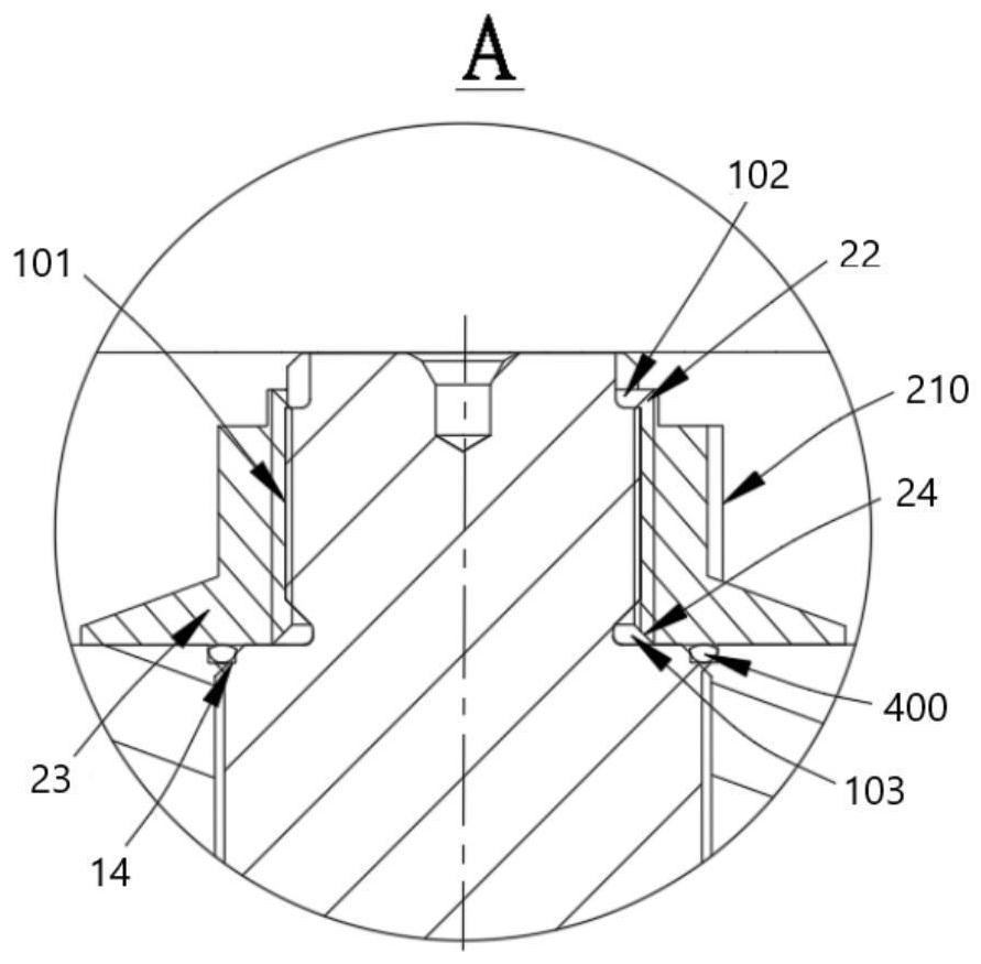
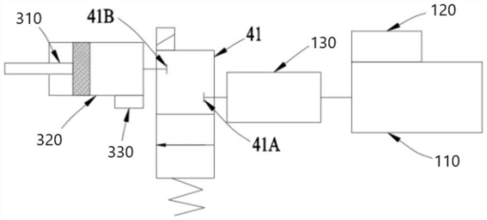
[0050]In order to make the purpose, technical solutions and advantages of the embodiments of the present invention clearer, the technical solutions in the embodiments of the present invention will be clearly and completely described below in conjunction with the drawings in the embodiments of the present invention. It should be noted that in this article, relational terms such as first and second are only used to distinguish one entity or operation from another entity or operation, and do not necessarily require or imply that there is a relationship between these entities or operations. There is no such actual relationship or order between them. In describing the present invention, it is to be understood that the terms "center", "upper", "lower", "front", "rear", "left", "right", "vertical", "horizontal", The orientations or positional relationships indicated by "top", "bottom", "inner", "outer", etc. are based on the orientations or positional relationships shown in the drawi...


PUM


Abstract

The invention belongs to the technical field of shaft end locking, solves the technical problems that in the prior art, shaft end locking is not stable, and rotating shaft operation may fail, and provides a rotating shaft locking assembly, a speed reducer and a new energy automobile. The rotating shaft locking assembly comprises a rotating shaft and a locking nut, wherein the free end of the rotating shaft is provided with a step section, external threads are arranged on the peripheral surface of the step section, and a notch is formed in the tail end of the free end; the locking nut comprises a nut body, a through hole with an internal thread in threaded connection with the external threads is formed in the nut body, a sheet is arranged at the position, corresponding to the notch, of the tail end of the first free end of the nut body, and the sheet is fixed in the notch through fixing operation. The rotating shaft locking assembly, the speed reducer and the new energy automobile have the advantages that the shaft end is locked stably, and reliable operation of the rotating shaft is guaranteed.

Description

technical field [0001] The invention relates to the technical field of shaft end locking, in particular to a shaft locking assembly, a reducer and a new energy vehicle. Background technique [0002] At present, the shaft end locking structure is widely used in all walks of life, especially the automobile industry. As one of the most widely used means of transportation, automobiles have gradually entered every family and become one of the must-haves for the family. [0003] Among auto parts, the transmission and reducer, which are the core parts of traditional fuel vehicles and new energy vehicles, use the engine or motor to generate power, and convert the power into different torques through the meshing of different gears in the transmission or reducer After the speed and speed, the wheels are directly driven forward. The transmission or reducer is connected to the output shaft through the output flange. The locking of the end adjacent to the output shaft and the flange is v...

Claims


Application Information

Patent Timeline
IPC IPC(8): F16H57/00F16H57/04F16H63/32
CPCF16H57/0025F16H57/0435F16H63/32F16H2063/321
Inventor 苏倩唐亚卓
Owner 阿姆特上海新能源科技有限公司
Why Eureka
Try Eureka