Installation-free bed guardrail
An installation-free, guardrail technology, applied in the direction of beds, other seating furniture, home appliances, etc., can solve the problems of inconvenience, spending a lot of time to install, and will not install bed guardrails, etc., to achieve strong stability, convenient pre-installation, convenient The effect of installation
- Summary
- Abstract
- Description
- Claims
- Application Information
AI Technical Summary
Problems solved by technology
Method used
Image
Examples
Embodiment 1
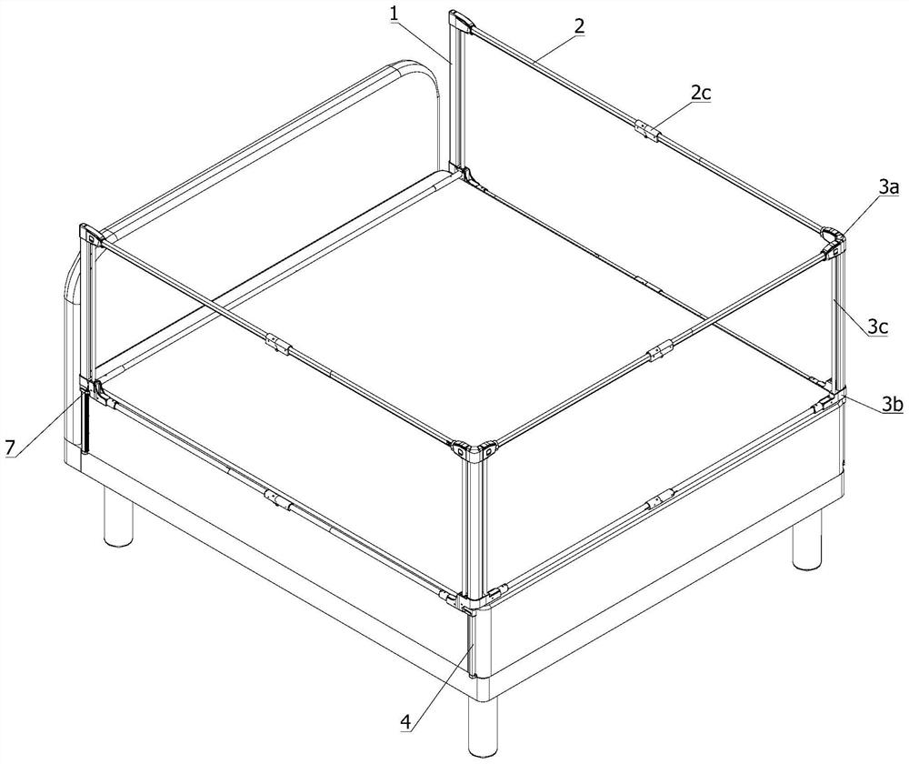
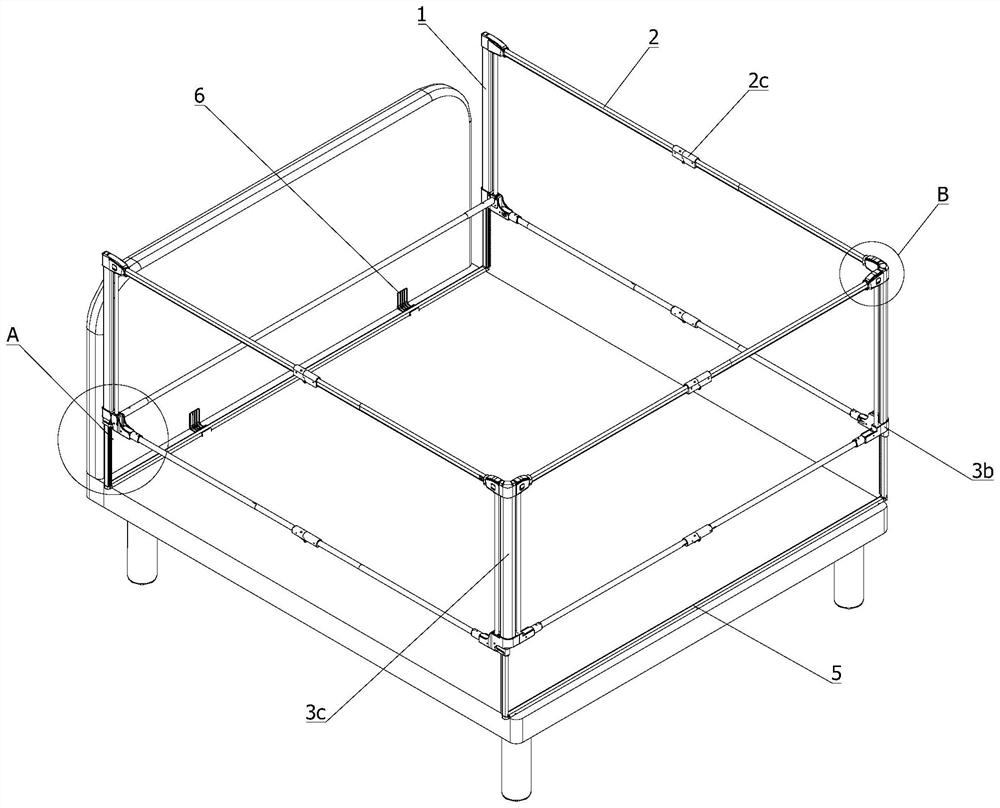
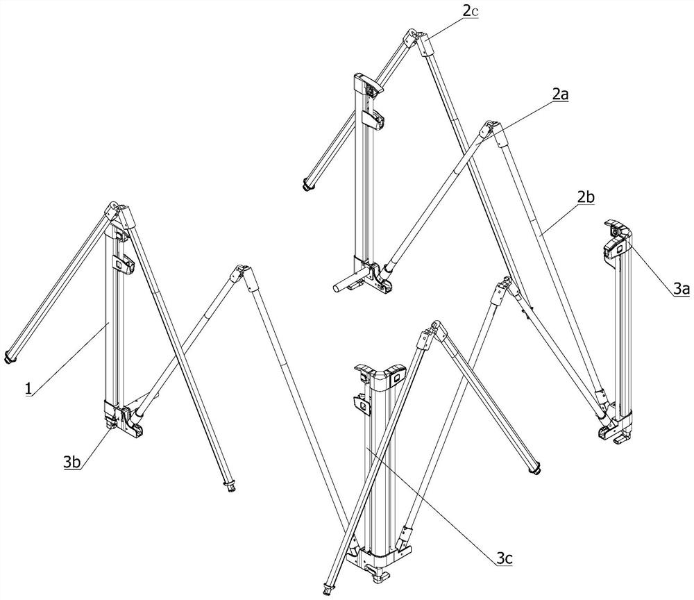
[0053] Such as Figure 1 to Figure 14 As shown, the installation-free bed guardrail of this embodiment is applied to a bed with a mattress. The bed guardrail includes a support and a guardrail. The support is sandwiched between the bed and the mattress, and the guardrail is fixedly connected to the support; its features That is, the supports are arranged at both ends of the bed, the guardrails are foldable, and when the guardrails are unfolded, they are combined with the supports to form a whole that surrounds the mattress.
[0054] Because the guardrail surrounds the entire mattress through the support, and the guardrail and the support are combined as a whole, so that the movement of the guardrail and the support relative to the mattress in any direction is restricted, so that the guardrail will not move during use. There will be no problems of misalignment and falling, and the guardrail is foldable for easy installation by customers, just unfold the guardrail.
[0055] Suc...
Embodiment 2
[0074] Compared with Example 1, such as Figure 11 ~ Figure 13 As shown, in this embodiment, there is a movable connection between the connecting plate 4 and the column 1, and an adjuster 7 that can adjust the height of the column 1 is provided between the connecting plate 4 and the second connecting piece 3b. The movable block 7a inside the second connector 3b, the side of the connecting plate 4 facing the movable block 7a is equipped with a first tooth bar 7b, the first tooth bar 7b extends along the length direction of the connecting plate 4, and the movable block 7a A second rack 7c is connected to the side facing the connecting plate 4, and the movable clamping block 7a is in a clamping state when the second rack 7c abuts against the first rack 7b.
[0075] Based on the embodiment, the connection plate 4 is combined with the column 1 to form a telescopic column, and then its length is locked by the adjuster 7, so that the height of the guardrail can be controlled. When ad...
Embodiment 3
[0078] Compared with Example 1, such as Figure 15 to Figure 21 As shown, the hinge 2c also has a second embodiment, the hinge 2c includes a third sleeve 2d1 and a fourth sleeve 2d4 whose ends are hinged to each other, the third sleeve 2d1 is sleeved on one end of the first rod 2a, The fourth sleeve 2d4 is sleeved on one end of the second rod part 2b; the end of the third sleeve 2d1 away from the first rod part 2a is provided with an outwardly extending post 2d2, and the fourth sleeve 2d4 is provided with a plug for insertion. The opening 2d5 where the post 2d2 is inserted, and the spring pin 2d3 is installed embeddedly inside the post 2d2, the execution part of the spring pin 2d3 protrudes from the outside of the post 2d2, and the fourth sleeve 2d4 is provided with a spring pin 2d3 for execution. When the third sleeve 2d1 and the fourth sleeve 2d4 are on the same line, the post 2d2 is inserted into the opening 2d5, and the spring pin 2d3 is inserted into the opening 2d6.
PUM
 Abstract
Description
Claims
Application Information
 - R&D
- Intellectual Property
- Life Sciences
- Materials
- Tech Scout
- Unparalleled Data Quality
- Higher Quality Content
- 60% Fewer Hallucinations
Browse by: Latest US Patents, China's latest patents, Technical Efficacy Thesaurus, Application Domain, Technology Topic, Popular Technical Reports.
© 2025 PatSnap. All rights reserved.Legal|Privacy policy|Modern Slavery Act Transparency Statement|Sitemap|About US| Contact US: help@patsnap.com


