COB light source mounting structure and method

A technology of installation structure and light source, applied in the direction of light source, light source fixing, semiconductor devices of light-emitting elements, etc., can solve the problems of low welding efficiency, troublesome installation of COB light source, unable to guarantee welding quality, etc., to improve welding quality, simple installation, The effect of simplifying the production process

Inactive Publication Date: 2017-06-23
ZHANGJIAGANG RADIANT TECH
View PDF3 Cites 0 Cited by
  • Summary
  • Abstract
  • Description
  • Claims
  • Application Information

AI Technical Summary

Problems solved by technology

This makes the installation of the COB light source more troublesome, and when the wires are directly welded to the lead-out end of the COB light source, only manual welding can be used, the welding efficiency is very low, and the welding quality cannot be guaranteed.

Method used


Image

  • COB light source mounting structure and method
  • COB light source mounting structure and method

Examples


Embodiment Construction

[0016] The specific implementation of the installation structure and method of a COB light source according to the present invention will be described in detail below with reference to the accompanying drawings.

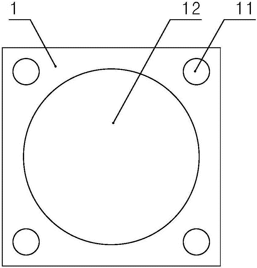
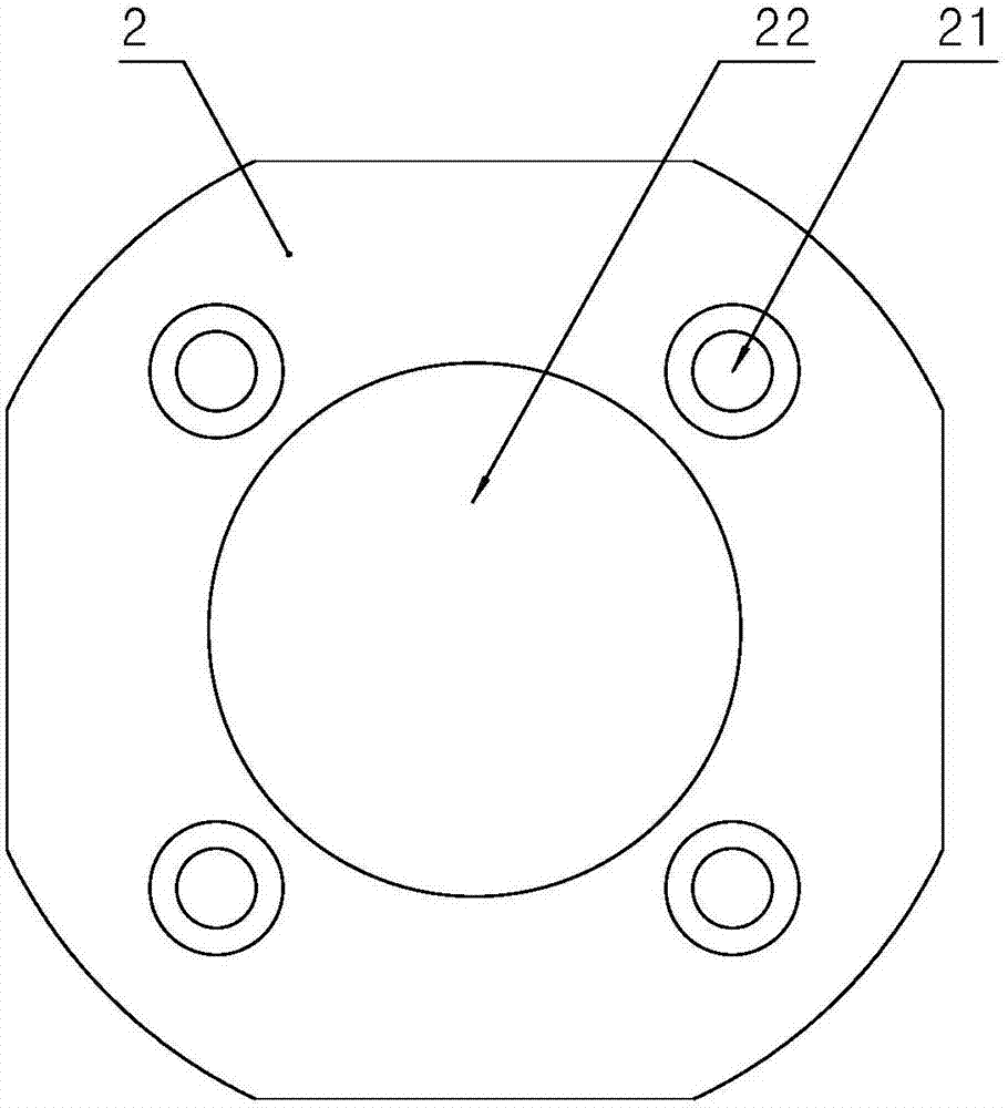
[0017] see Figure 1 to Figure 2 As shown, the installation structure of a COB light source according to the present invention includes: a COB light source 1, and a COB light source control circuit board 2. The COB light source control circuit board 2 is provided with a COB light source of the same size as the COB light source 1. The illumination window 22 matched with the light-emitting module, and the COB light source control circuit board 2 are also provided with electrical connection transfer holes 21 corresponding to the four leading ends of the COB light source one by one, and the four terminals of the COB light source 1 are connected by soldering. The leading end 11 is welded together with the four electrical connection transfer holes 21 on the COB light sourc...


PUM


Abstract

The invention discloses a COB light source mounting structure and method, and the pre-assembly and electric connection can be completed at one time. The light source mounting structure comprises a COB light source and a COB light source control circuit board. The light source mounting structure is characterized in that an irradiation window is arranged on the COB light source control circuit board, and the size of the irradiation window is matched with a COB light module of the COB light source; the COB light source control circuit board is further provided with an electric connection transfer hole corresponding to at least two leading-out terminals of the COB light source; and at least two leading-out terminals of the COB light source are correspondingly welded with the electric connection transfer hole on the COB light source control circuit board. The COB light source mounting structure and method also provides a method of mounting the COB light source for realizing the above mounting structure. The mounting structure can be widely used in various lamps using COB light source.

Description

technical field [0001] The invention relates to a method for installing an LED light source, in particular to a method for installing a COB light source. Background technique [0002] People in the industry know that the so-called COB light source is a high-efficiency integrated surface light source technology in which LED chips are directly attached to a mirror metal substrate with high reflectivity, and is usually packaged with ceramic materials. In the actual installation and production process, usually the lead-out wires are directly welded to the lead-out end of the COB light source, and then the COB light source is pressed to the installation position of the lamp with a pressure plate, and the COB light source cannot be pre-installed. (pre-assembled) on the compression plate. This makes the installation of the COB light source more troublesome, and when the wires are directly welded to the lead-out end of the COB light source, only manual welding can be used, the weld...

Claims


Application Information

Patent Timeline
Patent Type & Authority Applications(China)
IPC IPC(8): F21K9/20F21V19/00F21V23/00F21V23/06F21Y115/10
CPCF21V19/001F21V23/005F21V23/06
Inventor 陈来剑姜卫民李文俊侯丽娜严科明
Owner ZHANGJIAGANG RADIANT TECH
Why Eureka
Try Eureka