
Oral cavity disinfection device for stomatology department

A technology for oral disinfection and stomatology, which is applied in the direction of medicine equipment and other medical equipment. Efficient effect

Pending Publication Date: 2021-12-31
邱思敏
View PDF0 Cites 0 Cited by
  • Summary
  • Abstract
  • Description
  • Claims
  • Application Information

AI Technical Summary

Problems solved by technology

[0004] In order to overcome the disadvantages that the light in the patient's mouth is dark and it is inconvenient for medical staff to spray physiological saline, and if a large area of ​​disinfection is required, manual spraying requires more time and energy. The technical problem to be solved is: to provide a Oral disinfection device for stomatology with high efficiency for illuminating the patient's mouth

Method used


Image

  • Oral cavity disinfection device for stomatology department
  • Oral cavity disinfection device for stomatology department
  • Oral cavity disinfection device for stomatology department

Examples


Embodiment 1

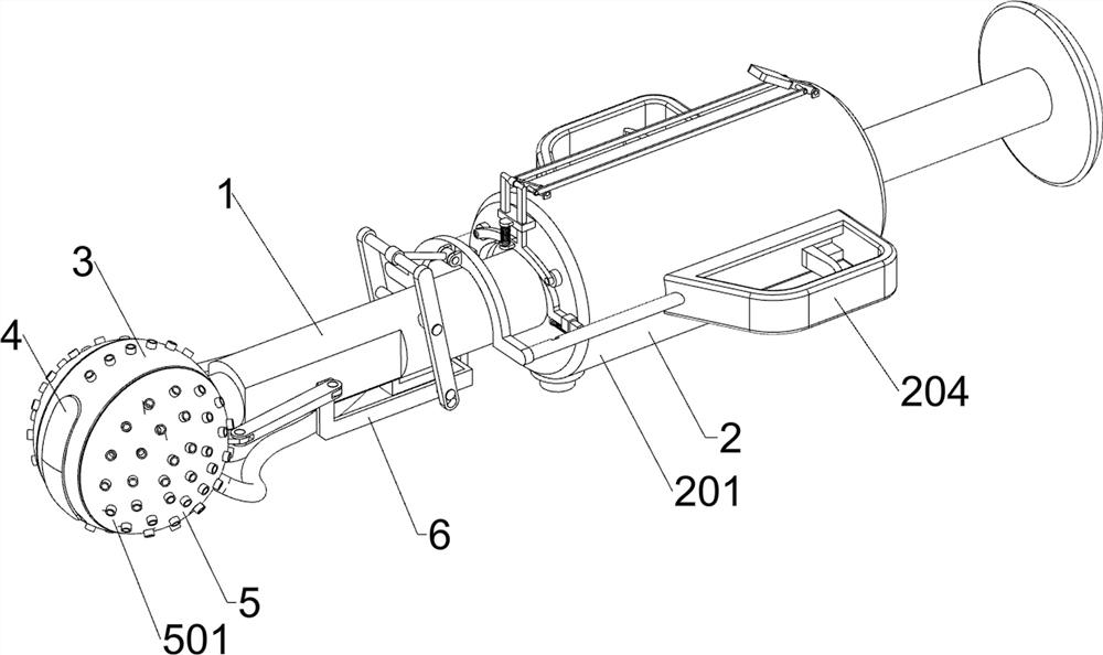
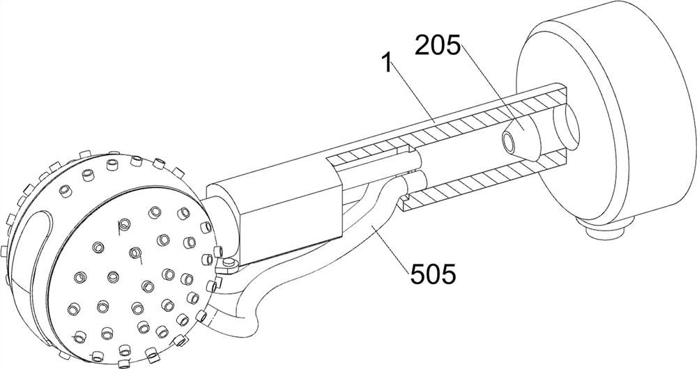
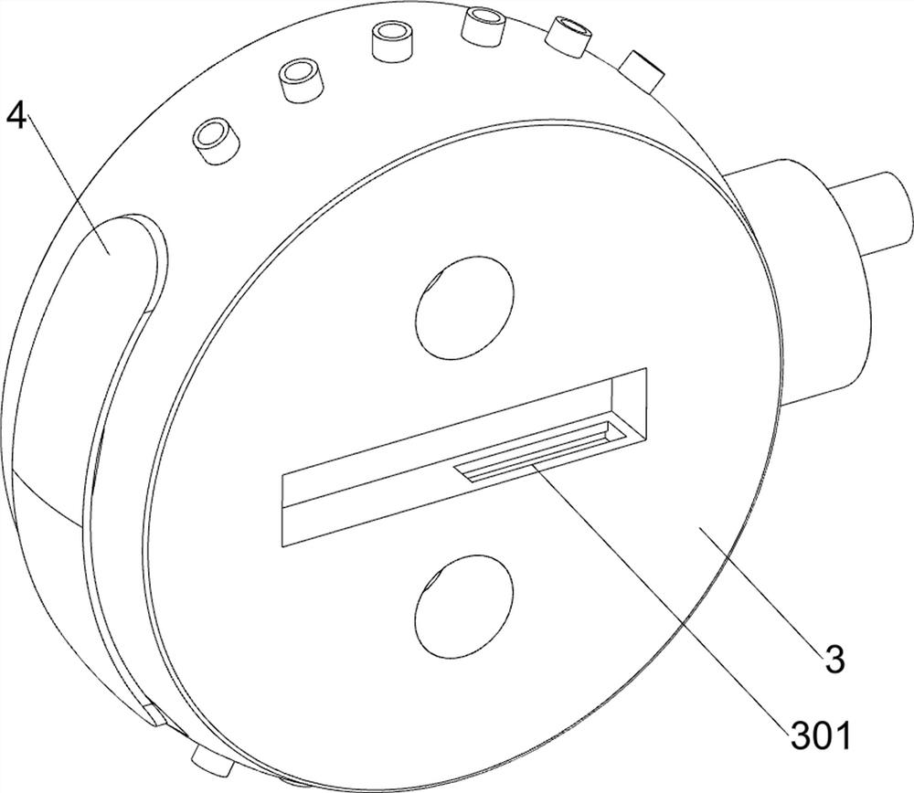
[0058] A kind of mouth disinfection device for stomatology, such as Figure 1-Figure 8 As shown, it includes a mounting rod 1, a pusher assembly 2, a first spray head 3, a lighting lamp 4 and a disinfection assembly 5, the pusher assembly 2 is provided on the right side of the installation rod 1, and the first spray head 3 is provided on the left side of the installation rod 1 A chute 301 is provided on the right side of the middle part of the front and rear sides of the first spray head 3 , an illuminating lamp 4 is provided on the left side of the first spray head 3 , and a disinfection assembly 5 is provided on the first spray head 3 .

[0059] The pusher assembly 2 includes a cylinder 201, a piston rod 202, a first spring 203, a fixed block 204 and a water outlet pipe 205. The right side of the installation rod 1 is provided with a cylinder 201, and the middle part of the right side of the cylinder 201 is slidingly provided with a piston rod. 202, a first spring 203 is pro...

Embodiment 2

[0063] On the basis of Example 1, such as figure 1 , figure 2 , Figure 9 and Figure 10 As shown, it also includes a stretching assembly 6, and the stretching assembly 6 includes a movable frame 601, a second connecting rod 602 and a lever 603, and the right side of the bottom of the mounting rod 1 is slidingly provided with a movable frame 601, and the left side of the movable frame 601 is connected to the A second connecting rod 602 is provided in a rotating manner between the second nozzles 501 , and a lever 603 is provided in a rotating manner on the upper right side of the installation rod 1 , and the lever 603 is slidingly matched with the movable frame 601 .

[0064] When the first nozzle 3 and the second nozzle 501 are spraying physiological saline, the medical staff can pull the upper part of the lever 603 to move to the right, so that the lever 603 rotates, and the lever 603 drives the movable frame 601 to move to the left, and the movable frame 601 passes throug...

Embodiment 3

[0068] On the basis of Example 2, such as figure 2 , image 3 , Figure 10 and Figure 11 As shown, a locking assembly 8 is also included. The locking assembly 8 includes a fixed sleeve 801, a special-shaped clamping rod 802 and a third spring 803. The middle part of the left side of the cylinder body 201 is symmetrically provided with a fixed sleeve 801 front and rear. The fixed sleeve 801 is all sliding A special-shaped clamping rod 802 is provided, and a third spring 803 is arranged between the special-shaped clamping rod 802 and the fixed sleeve 801 on the same side. The inner left part of the L-shaped sliding rod 701 has a clamping groove 804, and the special-shaped clamping rod 802 and the clamping groove 804 fit.

[0069] Also includes a reset assembly 9, the reset assembly 9 includes a contact frame 901, a fourth spring 902, a rotating rod 903, a pressure bar 904 and a connecting frame 905, and a contact frame 901 is rotated between the upper part of the special-sh...


PUM


Abstract

The invention relates to a disinfection device, in particular to an oral cavity disinfection device for the stomatology department. The technical problem to be solved is to provide the oral cavity disinfection device for the stomatology department, which can illuminate the oral cavity of a patient and is relatively high in efficiency. The oral cavity disinfection device for the stomatology department comprises: a mounting rod and a material pushing assembly, wherein the material pushing assembly is arranged on one side of the mounting rod; a first spray head which is arranged on the other side of the mounting rod, wherein sliding grooves are formed in the middles of the two sides of the first spray head; and an illuminating lamp which is arranged on one side of the first spray head. Through cooperation of the first spray head, the illuminating lamp, the second spray head, the material pushing assembly and the disinfection assembly, the oral cavity of a patient can be illuminated, and then the oral cavity of the patient can be automatically disinfected; and through cooperation of the opening assembly and the auxiliary assembly, when the first spray head and the second spray head spray normal saline, the second spray head can be driven to move towards the outer side, the spraying area is increased, and efficiency is high.

Description

technical field [0001] The invention relates to a disinfection device, in particular to an oral disinfection device for stomatology. Background technique [0002] When patients in the department of stomatology are treated, they generally disinfect the mouth first to avoid aggravation of the condition and facilitate subsequent treatment. At present, medical staff generally put physiological saline into the container, and then spray the physiological saline on the patient's mouth middle. [0003] Because the light in the patient's mouth is dark, it is inconvenient to spray, and if the patient's mouth needs to be disinfected on a large scale, manual spraying needs to consume more time and energy, and the efficiency is not high. An oral disinfection device for stomatology with high efficiency for illuminating the patient's oral cavity. Contents of the invention [0004] In order to overcome the disadvantages that the light in the patient's mouth is dark and it is inconvenien...

Claims


Application Information

Patent Timeline
Patent Type & Authority Applications(China)
IPC IPC(8): A61M31/00
CPCA61M31/00A61M2205/587
Inventor 邱思敏
Owner 邱思敏
Learn More