Simple delayed stripping mechanism

A simple, block-removing technology, which is applied in the direction of pushing out equipment, can solve problems such as unsmooth discharging, low work efficiency, and lack of smooth discharging, so as to improve the smoothness of discharging and meet the needs of use

Pending Publication Date: 2021-12-31
苏州正盛科技有限公司
View PDF0 Cites 0 Cited by
  • Summary
  • Abstract
  • Description
  • Claims
  • Application Information

AI Technical Summary

Problems solved by technology

[0002] In the production process of the strip, it is necessary to use a punching die to punch the strip. Due to the high requirements of the product plane, it is necessary to hold the stripping block to avoid deformation during punching; the existing punching die does not have The function of smooth material discharge. After the existing punching die cuts the product, when the upper die seat on the mold is disengaged upwards, the punched product will be pushed into the material belt, causing the product to be stuck on the material belt, and the material is discharged. Unsmooth, need to use a tool alone to eject the punched product, low work efficiency, time-consuming and laborious, can not meet the needs of use, so we propose a simple delay unloading mechanism to solve the above problems

Method used


Image

  • Simple delayed stripping mechanism
  • Simple delayed stripping mechanism
  • Simple delayed stripping mechanism

Examples


Embodiment Construction

[0023] The following will clearly and completely describe the technical solutions in the embodiments of the present invention with reference to the accompanying drawings in the embodiments of the present invention. Obviously, the described embodiments are only some, not all, embodiments of the present invention.

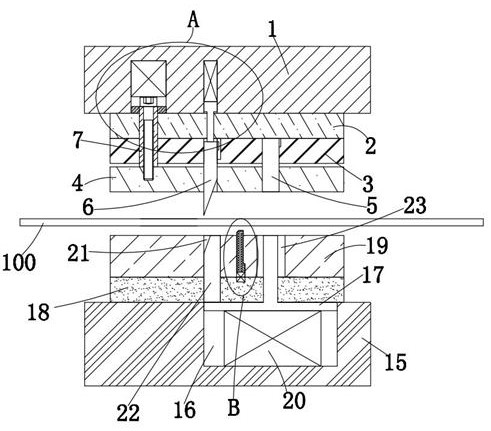
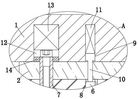
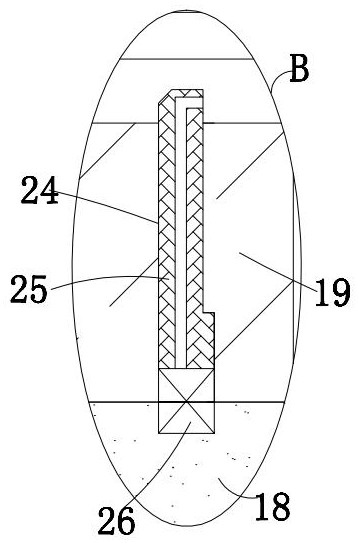
[0024] refer to Figure 1-6, a simple time-delay stripping mechanism, including an upper mold base 1 and a lower mold base 15, a material belt 100 is provided between the upper mold base 1 and the lower mold base 15, and an upper backing plate is fixedly connected to the bottom of the upper mold base 1 2. The top of the lower mold base 15 is fixedly connected with the lower backing plate 18, the bottom of the upper backing plate 2 is fixedly connected with the splint 3, the top of the lower backing plate 18 is fixedly connected with the lower formwork 19, and the lower part of the splint 3 is provided with a pressure plate 4. The bottom of the upper backing plate 2 i...


PUM


Abstract

The invention discloses a simple delayed stripping mechanism. The simple delayed stripping mechanism comprises an upper die base and a lower die base, wherein a material belt is arranged between the upper die base and the lower die base, the bottom of the upper die base is fixedly connected with an upper base plate, the top of the lower die base is fixedly connected with a lower base plate, the bottom of the upper base plate is fixedly connected with a clamping plate, the top of the lower base plate is fixedly connected with a lower die plate, a material pressing plate is arranged below the clamping plate, a shearing punch is fixedly connected to the bottom of the upper base plate, the bottom of the shearing punch extends to the position below the clamping plate, the material pressing plate slidably sleeves the shearing punch, a first rectangular groove is formed in the top of the clamping plate, an inclined wedge is slidably sleeved with the first rectangular groove, the bottom of the inclined wedge extends to the position below the material pressing plate, and the material pressing plate is sleeved on the inclined wedge in a sliding manner. According to the simple delayed stripping mechanism, the material belt can be conveniently and rapidly punched, the phenomenon that a product is jacked into the material belt can be effectively avoided in the mode that the product is pushed out in a delayed mode, the discharging smoothness is improved, and the use requirement is met.

Description

technical field [0001] The invention relates to the technical field of a time-delayed material removal mechanism, in particular to a simple time-delayed material removal mechanism. Background technique [0002] In the production process of the strip, it is necessary to use a punching die to punch the strip. Due to the high requirements of the product plane, it is necessary to hold the stripping block to avoid deformation during punching; the existing punching die does not have The function of smooth material discharge. After the existing punching die cuts the product, when the upper die seat on the mold is disengaged upwards, the punched product will be pushed into the material belt, causing the product to be stuck on the material belt, and the material is discharged. It is not smooth, and it is necessary to use a tool alone to eject the punched product. The work efficiency is low, and it is time-consuming and laborious, which cannot meet the needs of use. Therefore, we have...

Claims


Application Information

Patent Timeline
IPC IPC(8): B21D28/14B21D45/04
CPCB21D28/14B21D45/04
Inventor 范广林郑利骏蔡坤明
Owner 苏州正盛科技有限公司
Why Eureka
Try Eureka