Supercharge Your Innovation With Domain-Expert AI Agents!

Auxiliary guide sleeve synchronous clamping and rotating structure applied to shaft machining

A rotating structure and synchronous clamping technology, applied in metal processing equipment, metal processing machinery parts, clamping, etc., can solve the problems of inability to process the shaft, large torque, poor adaptability, etc., to reduce cumbersomeness, reduce torque, The effect of easy operation

Active Publication Date: 2021-12-31
中山市捷上同程数控机床有限公司
View PDF8 Cites 4 Cited by
  • Summary
  • Abstract
  • Description
  • Claims
  • Application Information

AI Technical Summary

Problems solved by technology

[0002] The lathe shaft mounting seat is used to install the strip-shaped shaft body and process the shaft body to assist the processing of the shaft body. Due to the compact structure of the existing shaft body mounting seat, the length of the processing lathe cannot be freely adjusted, and the comparison cannot be made. The long shaft is processed, and if the rear end of the shaft is long and the swing range is large during the rotation process, the rear end cannot realize synchronous rotation and clamping, and the torque is large, and the size of the lathe shaft mounting seat cannot be freely adjusted according to the length of the shaft. , poor adaptability

Method used


Image

  • Auxiliary guide sleeve synchronous clamping and rotating structure applied to shaft machining
  • Auxiliary guide sleeve synchronous clamping and rotating structure applied to shaft machining
  • Auxiliary guide sleeve synchronous clamping and rotating structure applied to shaft machining

Examples


Embodiment Construction

[0027] The following will clearly and completely describe the technical solutions in the embodiments of the present invention with reference to the accompanying drawings in the embodiments of the present invention. Obviously, the described embodiments are only some, not all, embodiments of the present invention. Based on the embodiments of the present invention, all other embodiments obtained by persons of ordinary skill in the art without making creative efforts belong to the protection scope of the present invention.

[0028] see Figure 1-6 , the present invention provides

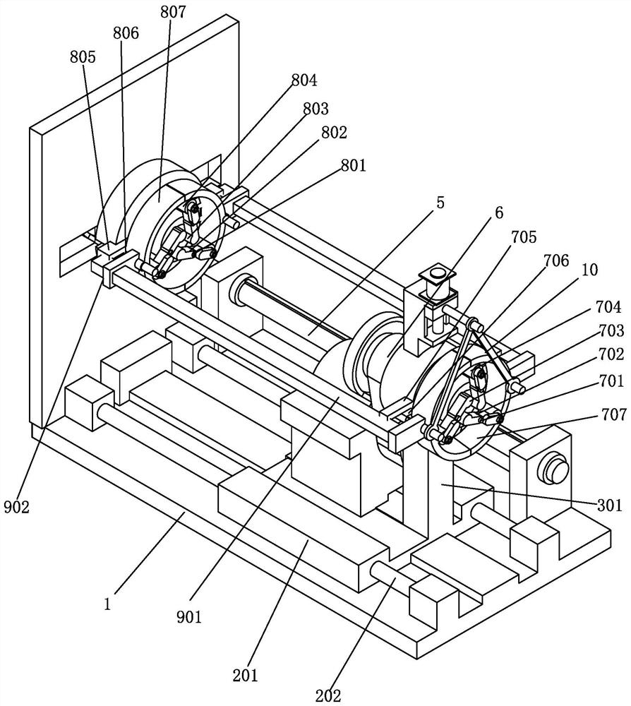
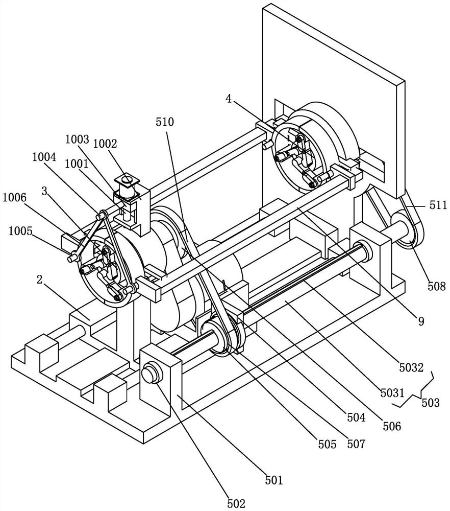
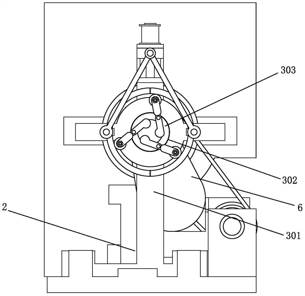
[0029] An auxiliary guide sleeve synchronous clamping and rotation structure applied to shaft processing, including a gantry support 1, a moving base assembly 2 is arranged on the gantry support 1, and a first rotating guide sleeve is provided on the moving base assembly 2 Assembly 3, the gantry bracket 1 is provided with a second rotating guide sleeve assembly 4 coaxial with the first rotating guide s...


PUM


Abstract

The invention discloses an auxiliary guide sleeve synchronous clamping and rotating structure applied to shaft machining, which comprises a gantry support, a movable base assembly is arranged on the gantry support, a first rotating guide sleeve assembly is arranged on the movable base assembly, the gantry support is provided with a second rotating guide sleeve assembly which is coaxial with the first rotating guide sleeve assembly and is arranged in a front-back spaced mode, and a synchronous spline transmission assembly capable of keeping synchronous rotation in the moving process in the same axis direction is arranged between the first rotating guide sleeve assembly and the second rotating guide sleeve assembly. Synchronous clamping and synchronous rotation of the front end and the rear end of a shaft can be achieved, the torque in the transmission process is reduced, swing of the shaft in the rotation process is reduced, the complexity that the front end and the rear end need to be manually clamped traditionally is reduced through synchronous clamping, operation is more convenient, and meanwhile the size of a lathe shaft installation base can be freely adjusted according to the length of the shaft, so that different shafts can be machined.

Description

technical field [0001] The invention relates to a lathe shaft mounting seat, in particular to an auxiliary guide sleeve synchronous clamping and rotating structure applied to shaft processing. Background technique [0002] The lathe shaft mounting seat is used to install the strip-shaped shaft body and process the shaft body to assist the processing of the shaft body. Due to the compact structure of the existing shaft body mounting seat, the length of the processing lathe cannot be freely adjusted, and the comparison cannot be made. The long shaft body is processed, and if the shaft body is long and the rear end swings a lot during the rotation process, the rear end cannot realize synchronous rotation and clamping, and the torque is large, and the size of the lathe shaft body mounting seat cannot be freely adjusted according to the shaft body length. , poor adaptability. [0003] Therefore, the existing lathe shaft mounting seat needs to be further improved. Contents of t...

Claims


Application Information

Patent Timeline
Patent Type & Authority Applications(China)
IPC IPC(8): B23Q3/06B23Q1/01B23Q1/26
CPCB23Q3/064B23Q1/012B23Q1/26Y02P70/10
Inventor 沈思杰向凌云张从鑫
Owner 中山市捷上同程数控机床有限公司
Features
  • R&D
  • Intellectual Property
  • Life Sciences
  • Materials
  • Tech Scout
  • Unparalleled Data Quality
  • Higher Quality Content
  • 60% Fewer Hallucinations
Learn More