Eureka AIR delivers breakthrough ideas for toughest innovation challenges, trusted by R&D personnel around the world.

Fast stretching or retracting, safe positioning and synchronous leg device, unipod and tripod

A safe positioning and fast technology, applied in the field of tripods, can solve problems such as excessive clearance, broken tripod equipment, and easy topple over

Pending Publication Date: 2021-12-31
周文化
View PDF0 Cites 1 Cited by
  • Summary
  • Abstract
  • Description
  • Claims
  • Application Information

AI Technical Summary

Problems solved by technology

In addition, using the above-mentioned structure to lock the leg tubes is easy to loosen, because they all use the principle of pressing and locking, but this kind of locking is not locking in the real sense, and even if the so-called locking has been carefully achieved, every The legs of each section of the group may still be locked due to frequent use or excessive gaps or heavy loads, and as long as one of the telescopic tubes is loose, one of the legs of the tripod can be retracted at any time. The tripod is not stable, it is easy to fall over, and it may even break the equipment on the tripod
In addition, the weight of the above-mentioned tripod support equipment is also very limited. In order to solve the problem of small load-bearing legs, many manufacturers choose more expensive materials, and some make the legs thicker and thicker. However, this method will only increase slightly. A little friction or a slight increase in load-bearing can not fundamentally solve the problem of heavy-duty legs
Also, especially the tripod legs in the known products or prior art cannot be synchronized quickly and simultaneously when stretching out or retracting, and cannot be positioned safely at multiple points.

Method used


Image

  • Fast stretching or retracting, safe positioning and synchronous leg device, unipod and tripod
  • Fast stretching or retracting, safe positioning and synchronous leg device, unipod and tripod
  • Fast stretching or retracting, safe positioning and synchronous leg device, unipod and tripod

Examples


Embodiment 1

[0049] Embodiment 1, the connection relationship of the foot pipe device:

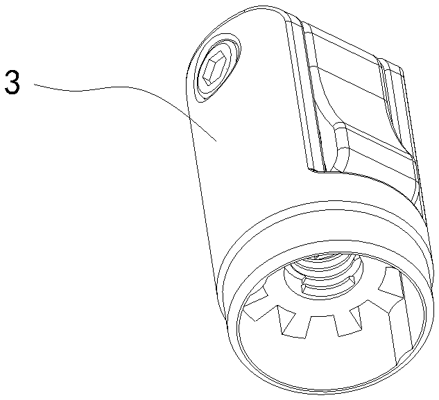
[0050] combine Figure 1-9 As shown, it includes a foot tube device that can be quickly extended or retracted, safely positioned and synchronized, including a connecting tube 3, an outer tube 6, and a first inner tube 8, and cooperates to form a plurality of stretchable tubes. The connecting tube 3 Connect the outer tube 6, one end of the first inner tube 8 is installed with a positioning lock device 11, the other end of the first inner tube 8 is provided with a foot 13, and one side of the foot 13 is provided with a controlled pressing member 16 Whether to cooperate with the positioning lock device 11 to unlock the key 18.

[0051] Further, the side of one end of the outer tube is provided with a locking hole A19, and one end of the outer tube is provided with an interface sleeve 21, the upper part of the interface sleeve 21 is provided with an external thread, and the end of the external thread is p...

Embodiment 2

[0054] Embodiment 2, positioning lock device 11:

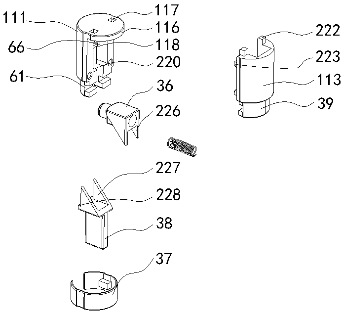
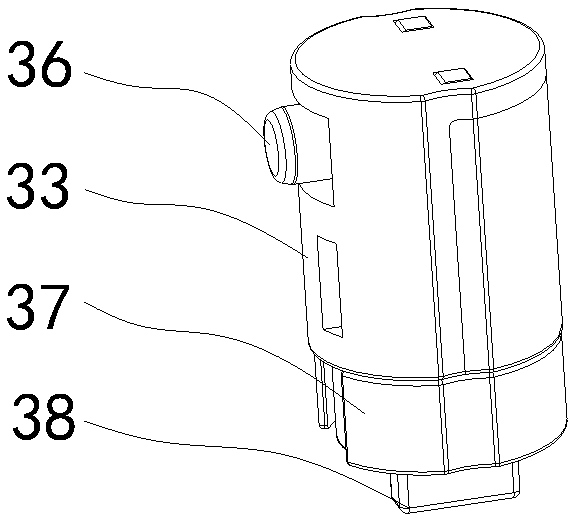
[0055] combine figure 2 , 3 As shown, the positioning lock device 11 includes a lock body A33, a positioning tongue A36, a limit card A37, an elastic member and a shovel A38, and one end of the lock body A33 is provided with a step A39, at least one hole A61, and the hole A61 is connected to the position limiter. The mouth A27 is fixedly connected by point pressing of the limit card A37, one end of the shovel block A38 matches and abuts against the positioning tongue A36, and one end of the pressing part is provided with a limit head 63, and the limit head 63 abuts against the other end of the shovel block A38 . The side of the lock body A33 has an orifice A66 to cooperate with the positioning tongue A36, and an elastic member is arranged between the positioning tongue A36 and the inside of the lock body A33. Chamber.

[0056] Further, for positioning lock device 11, in order to quickly release the mold and facilitate ass...

Embodiment 3

[0057] Embodiment 3, limit lock device 9:

[0058] combine Figure 4 , 5 As shown, further, the limit lock device 9 includes a lock body B69, a positioning tongue B73, a locking tongue 77, a limit card B78, an elastic member and a shovel block B79, and one end of the lock body B69 has a step B83 and at least one hole B86, the mouth hole B86 and the limit port B28 are connected by the limit card B78 or fixed by point pressure, one end of the shovel block B79 matches and abuts with the positioning tongue B73, and the side of the lock body B69 has a hole B87 and a positioning tongue B73 cooperates, and elastic member is arranged between positioning tongue B73 and lock body B69, and the upper part of positioning tongue B73 can be T-shaped opening 88, and locking tongue 77 is installed in T-shaped opening 88, between locking tongue 77 and positioning tongue B73 An elastic member is provided, and the sliding direction of the locking tongue 77 is opposite to that of the positioning...


PUM


Abstract

The invention discloses a fast stretching or retracting, safe positioning and synchronous leg device, a unipod and a tripod. The fast stretching or retracting, safe positioning and synchronous leg device comprises a tube connecting piece, an outer tube, at least one second inner tube and / or first inner tube which are matched to form a plurality of sections or a plurality of groups of telescopic legs, the tube connecting piece is connected with the outer tube, one end parts of the first inner tubes are provided with positioning lock devices, the other end parts of the first inner tubes are provided with feet, and one side parts of the feet are provided with keys or switches for controlling whether abutting pieces or pull wires are matched with the positioning lock devices for unlocking. A positioning tongue part penetrates through a transverse positioning structure of a leg positioning hole for positioning, so that the legs do not need to be unlocked in advance before stretching or retracting, the legs can stretch or retract only by pressing the keys, and safe and automatic positioning can be quickly realized; and in addition, the legs can form the tripod and the unipod, and about one third of load bearing can be increased on the basis of common universal legs.

Description

technical field [0001] The invention relates to the technical field of tripods, more specifically, to a leg tube device, a monopod and a tripod that can be extended or retracted quickly, positioned safely and synchronized. Background technique [0002] The tripods in the prior art are almost all made up of several telescopic leg tubes, and each segment of the leg tubes is basically locked by threads or eccentric bumps or eccentric tubes, and some even use bolts to tighten them. However, the above-mentioned technical structure must be unlocked in advance when the leg tube is extended or retracted, then pulled out or retracted, and then locked again, which is very inconvenient to operate during use. It has some deficiencies or has some more serious shortcomings for a long time. The "Quick retractable positioning and easy to open quadruped or tripod" I applied for on 20210115 is an exception to another locking structure. In addition, using the above-mentioned structure to loc...

Claims


Application Information

Patent Timeline
Patent Type & Authority Applications(China)
IPC IPC(8): F16M11/32F16M11/16
CPCF16M11/32F16M11/16
Inventor 周文化
Owner 周文化
Why Eureka
Eureka Blog
Learn More