
Photovoltaic direct-current transformer topological structure and non-locking fault ride-through control method

A DC transformer and topology technology, applied in the direction of DC power input conversion to DC power output, photovoltaic power generation, photovoltaic modules, etc., can solve problems such as affecting power supply reliability, increasing Boost-level losses, and long start-up process of DC transformers. The effect of improving power supply reliability and reducing costs

Active Publication Date: 2021-07-09
STATE GRID JIANGSU ELECTRIC POWER CO ELECTRIC POWER RES INST +1
View PDF2 Cites 0 Cited by
  • Summary
  • Abstract
  • Description
  • Claims
  • Application Information

AI Technical Summary

Problems solved by technology

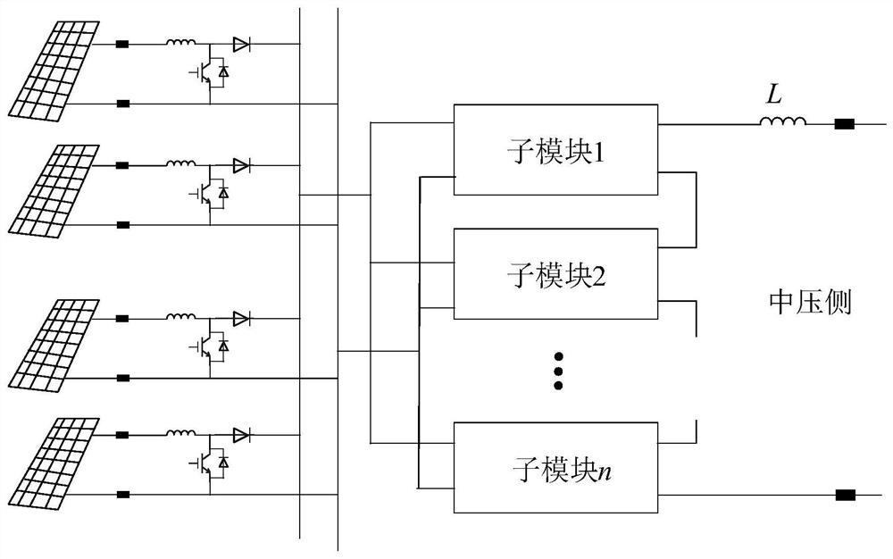
The common Boost circuit controls the output voltage of the photovoltaic unit to realize MPPT control, but increases the loss of the Boost stage, thereby reducing the efficiency of the whole machine
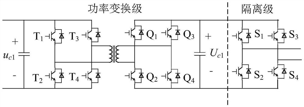
At the same time, the traditional IPOS sub-module of the DC transformer mostly adopts a full bridge circuit or a dual active bridge structure, and the output side is directly connected in series to form a centralized capacitor. The protection scheme not only has a large impact on the equipment, but also needs to be equipped with a DC circuit breaker, and the voltage on the medium voltage side becomes zero. When the fault is cleared and the power supply needs to be restored, the DC transformer needs to go through a long startup process, which affects the reliability of the power supply.

Method used


Image

  • Photovoltaic direct-current transformer topological structure and non-locking fault ride-through control method
  • Photovoltaic direct-current transformer topological structure and non-locking fault ride-through control method
  • Photovoltaic direct-current transformer topological structure and non-locking fault ride-through control method

Examples


Embodiment Construction

[0046] In order to make the object, technical solution and advantages of the present invention clearer, the technical solution of the present invention will be clearly and completely described below in conjunction with the drawings in the embodiments of the present invention. The embodiments described in this application are only some embodiments of the present invention, not all embodiments. Based on the spirit of the present invention, all other embodiments obtained by persons of ordinary skill in the art without making creative efforts all belong to the protection scope of the present invention.

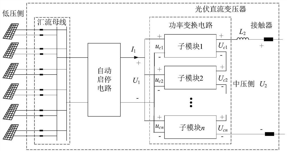
[0047] Such as figure 1 As shown, the topology of the photovoltaic step-up DC transformer disclosed in this application includes: a bus bar, a power conversion circuit, an output inductor and an output contactor.

[0048] Multiple groups of photovoltaic panels are respectively connected to the busbar through the outlet switch, and the busbar is connected to the input end of the p...


PUM


Abstract

The invention discloses a photovoltaic direct-current transformer topology structure and a non-lockout fault ride-through control method. The direct-current transformer topology is divided into three stages of circuits: the first stage is a power conversion circuit of an input-parallel output-series (IPOS) structure, the second stage is an automatic start-stop circuit, and the third stage is a bus bar and an outgoing line switch. During normal operation, the automatic start-stop circuit is in a non-working state, so that the loss is reduced, and the overall efficiency is improved. Meanwhile, the power conversion circuit comprises an isolation stage circuit, so that fault ride-through is realized. In fault ride-through control, the number of positive and negative voltage input sub-modules is adjusted through an isolation stage circuit, so that direct-current fault current is rapidly controlled to be zero, and continuous stable operation of equipment during a fault period can be realized. Meanwhile, the medium-voltage side capacitor voltage is maintained through the power conversion circuit during the fault period, so that quick recovery after the fault is cleared is realized, and the system recovery time is shortened. And because locking is not performed during a fault period, a medium-voltage side does not need a direct-current circuit breaker, and the application cost is reduced.

Description

technical field [0001] The invention belongs to the technical field of DC power transmission, and in particular relates to a photovoltaic DC transformer topology and a non-blocking fault ride-through control method. Background technique [0002] Compared with the traditional AC converging system, the medium-voltage DC converging networking system of large-scale photovoltaic power stations has higher efficiency, and it is a potential effective way to develop photovoltaic resources on a large scale in the future. The medium-voltage DC transformer is one of the core equipment for building a photovoltaic medium-voltage DC collection system. The capacity and cost of the traditional single-pole centralized power station are limited to a certain extent. At present, it is gradually developed to gather energy to the low-voltage DC bus through decentralized DC modules. [0003] Existing photovoltaic medium-voltage DC collection systems generally adopt a three-stage circuit. The first...

Claims


Application Information

Patent Timeline
Patent Type & Authority Applications(China)
IPC IPC(8): H02M3/335H02M1/32H02S40/34H02J3/38
CPCH02M3/3353H02M1/32H02S40/34H02J3/381H02J2300/26Y02E10/56
Inventor 刘瑞煌史明明杨景刚张宸宇袁宇波葛雪峰姜云龙肖小龙陈舒缪惠宇司鑫尧苏伟郭佳豪
Owner STATE GRID JIANGSU ELECTRIC POWER CO ELECTRIC POWER RES INST
Learn More