Hinges for refrigerators
A hinge device, refrigerator technology, applied in door/window fittings, wing fan parts, folding panels, etc., can solve the problems of inconvenient adjustment, easy downward movement of the door body, small adjustment space, etc., and achieves compact structure and short length. , the effect of small adjustment space
- Summary
- Abstract
- Description
- Claims
- Application Information
AI Technical Summary
Problems solved by technology
Method used
Image
Examples
Embodiment 1
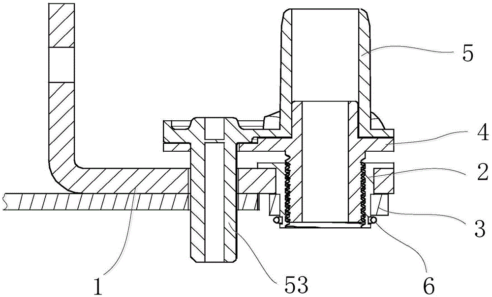
[0059] A refrigerator hinge device such as figure 1 As shown, it includes a hinge support 1 , a shaft sleeve 2 , a snap ring 3 , a hinge shaft 4 , a door bracket 5 and a retaining ring 6 .
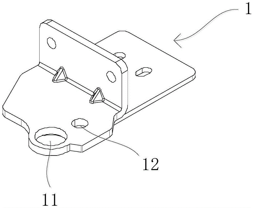
[0060] Among them, such as figure 2 As shown, the hinge support 1 is provided with a through hole 11 and a hinge support through hole 12 . The shaft sleeve 2 is sleeved on the hinge support 1 through the through hole 11 , and the shaft sleeve 2 can rotate in the through hole 11 .
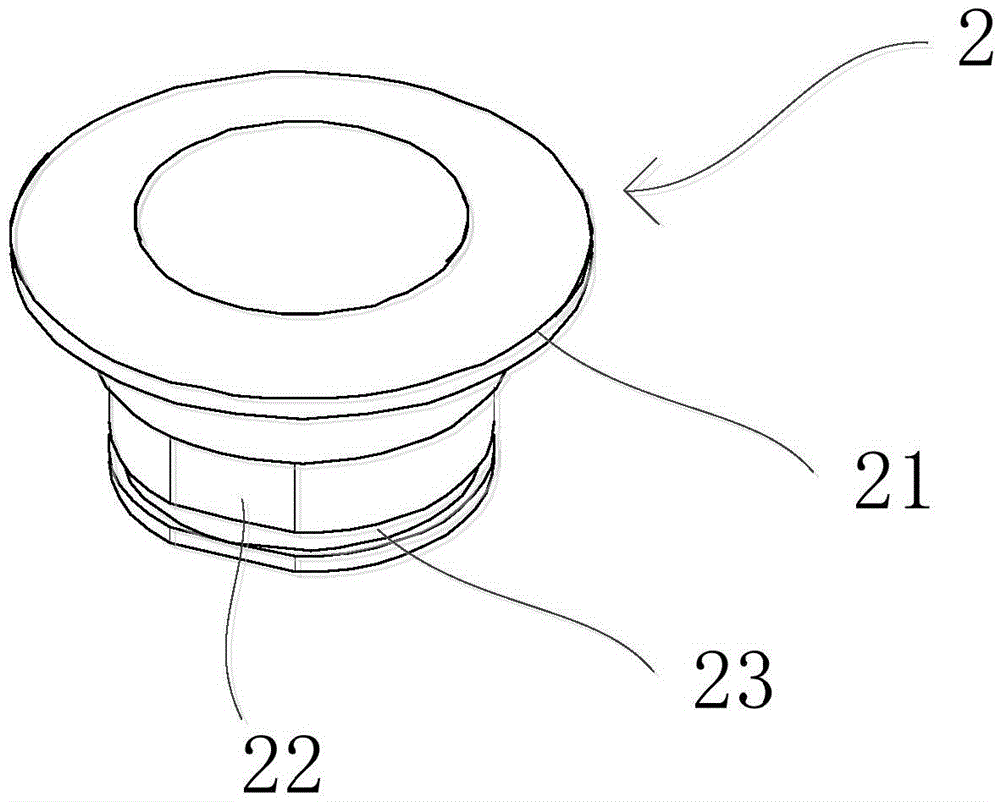
[0061] and, if figure 1 , 3As shown, the outer surface of one end of the sleeve 2 outside the through hole 11 extends outward to form a flange 21 , the lower end of the sleeve 2 is the protruding end, and the protruding end is located outside the through hole 11 . The lower side of the flange 21 abuts against the upper side of the hinge support 1 , so that the sleeve 2 is unidirectionally fixed on the upper side of the hinge support 1 .
[0062] The snap ring 3 is clamped on the protruding end of the lowe...
Embodiment 2
[0077] The structure of the hinge device for refrigerator in embodiment 2 is basically the same as embodiment 1, the difference is as Figure 10 Shown:
[0078] The hinge device does not include a clasp 3 , and the protruding end of the shaft sleeve 2 is only clamped with a retaining ring 6 . Moreover, the outer surface of the flange 21 is formed with an adjusting part for adjusting the rotation of the sleeve 2, that is, the outer surface of the flange 21 is designed as a polygon for easy adjustment, or the outer surface of the flange 21 is provided with knurling for easy adjustment.
Embodiment 3
[0080] The structure of the hinge device for refrigerator in embodiment 3 is basically the same as embodiment 1, the difference is that the installation position of the snap ring is different, such as Figure 11 Shown:
[0081] The snap ring 3 is clamped on the outer surface of the upper end of the shaft sleeve 2 , and the snap ring 3 is located between the flange 21 and the hinge support 1 . The snap ring 3 is used to adjust the rotation of the shaft sleeve 2, and the outer surface of the snap ring 3 is designed as a polygon for easy adjustment, or the outer surface of the flange 21 is provided with knurling for easy adjustment.
PUM
 Abstract
Description
Claims
Application Information
 - R&D
- Intellectual Property
- Life Sciences
- Materials
- Tech Scout
- Unparalleled Data Quality
- Higher Quality Content
- 60% Fewer Hallucinations
Browse by: Latest US Patents, China's latest patents, Technical Efficacy Thesaurus, Application Domain, Technology Topic, Popular Technical Reports.
© 2025 PatSnap. All rights reserved.Legal|Privacy policy|Modern Slavery Act Transparency Statement|Sitemap|About US| Contact US: help@patsnap.com


