
Cabinet slot position monitoring method based on indoor light source and method for positioning equipment in cabinet

A cabinet and slot technology, which is applied in the field of cabinet monitoring and equipment positioning, can solve problems such as inconvenient installation, small cabinet space, and signal interference, and achieve the effects of convenient maintenance and replacement, reduced polling frequency, and improved installation efficiency

Pending Publication Date: 2021-12-31
重庆红透科技有限公司
View PDF0 Cites 0 Cited by
  • Summary
  • Abstract
  • Description
  • Claims
  • Application Information

AI Technical Summary

Problems solved by technology

[0002] Existing cabinet capacity detection usually uses REID, which needs to paste REID radio frequency labels on each cabinet-entry equipment, and then read radio frequency signals through the REID reader in the cabinet, but the installation distance between devices is relatively short, and the space in the cabinet The narrowness causes the RF signal to be reflected multiple times, and the accuracy of the data read by the reading device is not high
In order to overcome the problem of signal interference, the REID radio frequency tag is connected to the detection equipment through a cable, but manual operation is required, which increases the possibility of mistakes. At the same time, since the radio frequency tag is connected to the cable, it will be cumbersome and easy for the equipment to enter and exit the cabinet. Causes damage to RF tags and cables
There is also the way of using luminous cross-radiation tubes, installing light-emitting sources and light-receiving devices on both sides of the installation slot of the cabinet to determine whether the slot is installed with equipment, but it is required that the cross-radiation light source and receiver can be accurately aligned. The installation requirements are high and the installation is inconvenient, especially when there are many cabinet slots. The more serious problem is that if the auxiliary L-shaped equipment brackets have been installed in the corresponding slots before the equipment is installed (the equipment), it will cause the incoming light to be blocked, no matter whether the equipment is installed or not, the L-shaped bracket will not be removed, causing the corresponding slots to be recognized as occupied, resulting in misjudgment

Method used


Image

  • Cabinet slot position monitoring method based on indoor light source and method for positioning equipment in cabinet
  • Cabinet slot position monitoring method based on indoor light source and method for positioning equipment in cabinet

Examples


Embodiment Construction

[0040] 1) Slot status monitoring

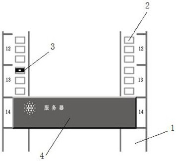
[0041] refer to figure 1 As shown in the figure, slots 12 to 14 on the equipment installation column 1 are shown. The equipment installation column 1 of the cabinet is provided with several equipment installation holes 2 for installing equipment panels, and each slot is divided into multiple slots. There are three equipment installation holes, generally three, that is, each slot generally corresponds to three equipment installation holes, and usually only one or at most two are used, so that at least one equipment installation hole will be vacated for the installation of photosensitive sensors 3. When equipment is installed on the slot, the equipment panel 4 will be fixed on the equipment installation hole, which will necessarily cover all the equipment installation holes of each slot.

[0042] A cabinet slot monitoring method based on an indoor light source, comprising the following steps:

[0043] Install corresponding photosensitive sen...


PUM


Abstract

The invention discloses a cabinet slot position monitoring method based on an indoor light source and a method for positioning equipment in a cabinet. A corresponding photosensitive sensor is installed corresponding to each slot position in an equipment installation column of the cabinet; an inductive probe of each photosensitive sensor is embedded into any one of a plurality of equipment panel mounting holes of the corresponding slot position; before and after the equipment is mounted, the equipment panel mounting holes are changed from a state not shielded by the equipment panel to a shielded state, so that the photosensitive sensor is changed from a light receiving state to a non-light receiving state, and different light sensing signals are generated and sent to a cabinet controller; and the cabinet controller identifies whether the slot position is occupied according to the photosensitive signal. According to the positioning method, the equipment is positioned by monitoring the occupation state of the slot position, whether the actual mounting slot position of the equipment is consistent with the preset slot position is judged according to the occupation state of the slot position, the accuracy of the positioning information is ensured, meanwhile, if the equipment is illegally detached from a rack and is removed from the rack, the system can automatically detect and give an alarm, and the safety of equipment assets is ensured.

Description

technical field [0001] The invention relates to the technical field of cabinet monitoring and equipment positioning. Background technique [0002] Existing cabinet capacity detection usually uses REID, which needs to paste a REID radio frequency label on each cabinet-entry device, and then read the radio frequency signal through the REID reader in the cabinet, but the installation distance between the devices is relatively short, and the space in the cabinet The narrowness causes the radio frequency signal to be reflected multiple times, and the accuracy of the data read by the reading device is not high. In order to overcome the problem of signal interference, the REID radio frequency tag is connected to the detection equipment through a cable, but manual operation is required, which increases the possibility of mistakes. At the same time, since the radio frequency tag is connected to the cable, it will be cumbersome and easy for the equipment to enter and exit the cabinet....

Claims


Application Information

Patent Timeline
Patent Type & Authority Applications(China)
IPC IPC(8): G01J1/00
CPCG01J1/00
Inventor 车世强
Owner 重庆红透科技有限公司
Learn More