
A high-voltage switchgear with defect monitoring and comprehensive control functions

A high-voltage switchgear and integrated control technology, applied in the field of high-voltage switchgear, can solve problems such as difficult integration, wrong analysis results, and difficult installation

Inactive Publication Date: 2020-05-22
李宏仁
View PDF7 Cites 0 Cited by
  • Summary
  • Abstract
  • Description
  • Claims
  • Application Information

AI Technical Summary

Problems solved by technology

Although this solution solves the safety problem of the monitoring system, the problem of incomplete monitoring parts, and the system is too complicated, the inventor further researched and found that: in field practice, if the thermal defect of the switchgear is checked according to the solution Inspection and analysis results often have errors, and it is often difficult to judge whether there is a defect and where the defect roughly occurs
In addition, in order to find various defects of the switchgear in time, people have done a lot of research and developed various types of testing equipment, but these equipments were installed later, thus changing the original structure and state of the switchgear. This will bring difficulties to the operation and maintenance of the switchgear in the future, and also increase the unsafe factors
Moreover, all kinds of monitoring equipment are often complex and self-contained systems. It is difficult to install so many different systems in one switchgear.
Although there was a point of view early on that it is hoped that various defect monitoring can be integrated in a unified system, but due to the great differences in the working principles, signal detection parts and detection methods of various defects, especially high-voltage part defect monitoring, it is difficult to Difficult to put together and difficult to implement
Because this problem has not been solved, most of the switch cabinets are still in the state of no monitoring

Method used


Image

  • A high-voltage switchgear with defect monitoring and comprehensive control functions
  • A high-voltage switchgear with defect monitoring and comprehensive control functions
  • A high-voltage switchgear with defect monitoring and comprehensive control functions

Examples


Embodiment 2

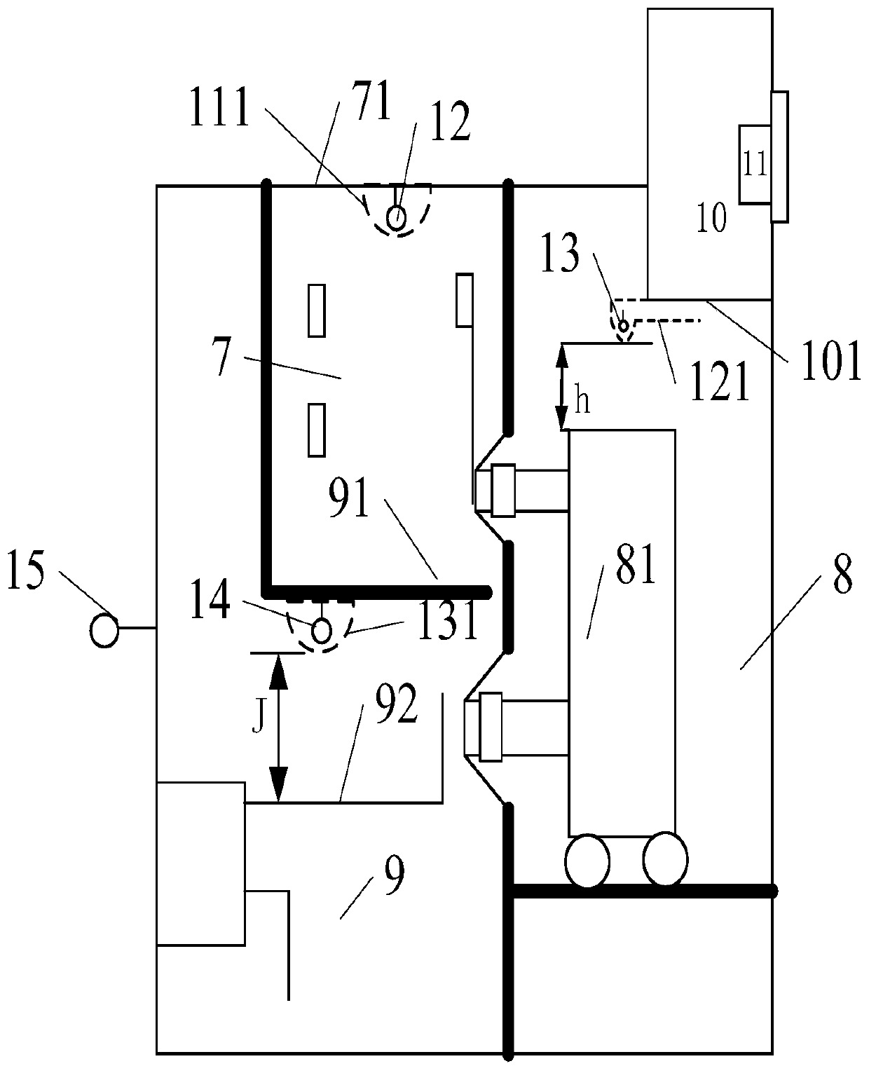
[0075] The structure of this embodiment 2 is basically the same as that of embodiment 1, the difference is that the measurement and control device 11 is also provided with 3 gas detection circuits, 3 ultrasonic detection circuits, 3 photoelectric detection circuits and corresponding sensors; there are 2 open circuits Coil current detection circuit and current sensor; 2 auxiliary switch action signal detection circuits; the measurement and control device 11 is also equipped with 2 switching output circuits 1DO and 2DO for controlling the entry and exit of the handcart of the circuit breaker; 2 circuits for controlling the operation of the grounding knife Switching output circuit 3DO, 4DO and 2 circuit breaker opening and closing position switching input circuit 1DI, 2DI, 2 circuit breaker working and testing position switching input circuit 3DI, 4DI, 2 grounding knife closing and opening position Switch value input circuit 5DI, 6DI, 1 route switch switching value input circuit 7...


PUM


Abstract

A high-voltage switchgear having defect monitoring and comprehensive control functions; the high-voltage switchgear comprises various compartments, as well as a comprehensive measurement and control device (11) that is mounted in a secondary chamber (10); in a cable chamber (9) of the switchgear, a first metal shielding case (131) used for mounting a sensor (14) is provided on a partition (91) between the cable chamber (9) thereof and a bus bar chamber (7); a first preset portion of the first metal shielding case (131) is located at a position having a height J 10-40 cm from a bottom wire outlet of a breaker (81) and facing the center line of a B-phase wire outlet of the breaker (81) at 0-15 cm, and at least a portion of the first preset portion is hollow; the present switchgear integrates insulation defect detection points with thermal defect detection, thereby further changing the switchgear into a smart power supply device capable of self-monitoring, self-protection, and self-control.

Description

technical field [0001] The invention relates to the field of power supply and distribution equipment, in particular to a high-voltage switchgear with defect monitoring and comprehensive control functions. Background technique [0002] High-voltage switchgear is commonly used equipment in power supply systems. Its structure usually includes: busbar room, circuit breaker room, cable room, secondary room and its internal components. When the switchgear is manufactured, the problem of how to monitor it is not considered, so the switchgear itself does not have a monitoring function and a corresponding structure. Due to manufacturing quality and equipment aging, various defects and failures will appear inside the switchgear during operation, such as overheating, insulation aging, discharge, flashover, mechanical jamming, action failure and other defects. These defects often end up developing into serious switchgear accidents. Among the various defects of the switchgear, the over...

Claims


Application Information

Patent Timeline
Patent Type & Authority Patents(China)
IPC IPC(8): H02B1/30H02B1/32H02B1/56H02B1/14G01D21/02
CPCG01D21/02H02B1/014H02B1/30H02B1/32H02B1/565G01D4/00G01D11/245H02B11/12H02B13/065Y04S20/30
Inventor 李宏仁肖红曾庆才杨帆冯权龙
Owner 李宏仁
Learn More