
Ice storage refrigeration system and refrigeration method thereof

A refrigeration system, ice storage technology, applied in air conditioning systems, heating methods, household heating and other directions, can solve the problems of high cost, large compression ratio, complex control, etc., to improve efficiency, avoid waste, and improve operation stability. Effect

Inactive Publication Date: 2012-01-11
江苏新七彩节能有限公司
View PDF4 Cites 12 Cited by
  • Summary
  • Abstract
  • Description
  • Claims
  • Application Information

AI Technical Summary

Problems solved by technology

[0027] The invention overcomes the problems that the conventional refrigerating unit cannot work under the ice-making condition, the compression ratio is large, the cost is high, and the control is complicated under the ice-making condition of the double-working condition refrigerating unit, and the cost of the refrigeration system can be reduced, and the ice-making efficiency and operation can be improved. stability

Method used


Image

  • Ice storage refrigeration system and refrigeration method thereof
  • Ice storage refrigeration system and refrigeration method thereof
  • Ice storage refrigeration system and refrigeration method thereof

Examples


Embodiment 1

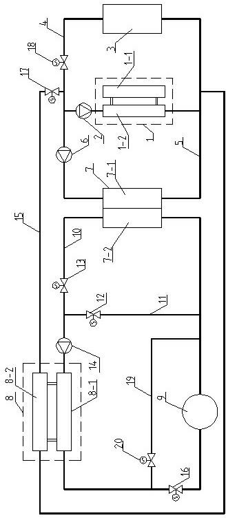
[0057] Such as figure 1 As shown, the present invention includes a refrigeration unit 1 , a terminal device 3 and a first chilled water pump 2 , and the first chilled water pump 2 , the evaporator 1 - 2 of the refrigeration unit 1 and the terminal device 3 are sequentially connected in a loop through a first pipeline 4 .

[0058] The third pipeline 5 is bypassed on the first pipeline 4 between the terminal device 3 and the first chilled water pump 2, and the second chilled water pump 6 and the thermal fluid channel 7-1 of the heat exchange device 7 are connected in series on the third pipeline 5 , the other end of the third pipeline 5 is bypassed on the first pipeline 4 between the terminal device 3 and the evaporator 1-2 of the refrigeration unit 1 .

[0059] The cold fluid channel 7-2 of the heat exchange device 7, the evaporator 8-1 of the ice making unit 8, and the ice storage device 9 are connected in a loop through the second pipeline 10, and the cold fluid channel 7-2 o...

Embodiment 2

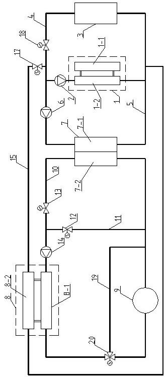
[0098] Such as figure 2 As shown, other connection methods are the same as Example 1, except that the fifth valve 20 and the sixth valve 16 in Example 1 are combined into a three-way valve 20, and the three-way valve 20 is connected in series between the second pipeline 10 and the sixth pipeline. 19 at the intersection.

Embodiment 3

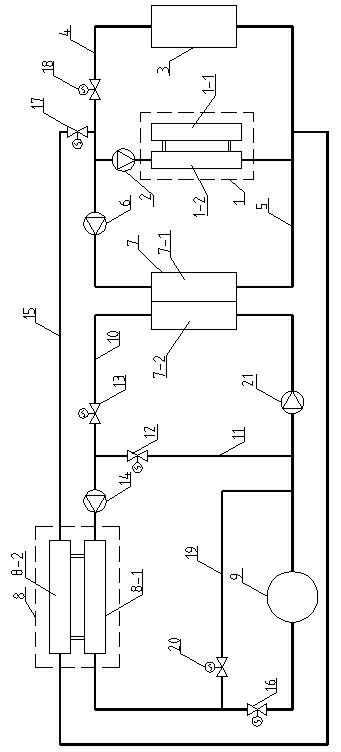
[0100] Such as image 3 As shown, other connection methods are the same as Example 1. In addition, another brine pump 21 is set on the second pipeline 10 connected to the input end of the cold fluid channel 7-2 of the heat exchange device 7, and the brine pump 21 can be changed to Flow type refrigerant pump.


PUM


Abstract

The invention discloses an ice storage refrigeration system and a refrigeration method thereof, which relate to the technical field of refrigeration air conditioners. The ice storage refrigeration system comprises a refrigeration unit, a tail end device, an ice making unit, a heat exchange device and an ice storage device, wherein an evaporator of the ice making unit, the ice storage device and acold fluid flow passage in the heat exchange device are connected by a pipeline loop; a hot fluid flow passage in the heat exchange device is connected with the loop of the tail end device via a pipeline; a loop between the condenser of the ice making unit and the evaporator of the refrigeration unit is provided with a pipeline; and the cooling water of the condenser of the ice making unit is supplied after being precooled to 2-20 DEG C by the refrigeration unit. According to the ice storage refrigeration system, the problems that the traditional refrigeration unit can not work under the ice making working condition and a refrigeration unit of double working conditions has big compression ratio, high cost and the like and is complex to control under the ice making working condition are solved, the cost of the refrigeration system can be lowered, and ice making efficiency and operation stability are improved.

Description

technical field [0001] The invention relates to the technical field of refrigeration, in particular to the technical field of refrigeration and air conditioning. Background technique [0002] Conventional refrigeration systems are generally composed of refrigeration equipment, cold source devices, terminal devices, auxiliary equipment, connecting pipelines, and control systems. The most widely used refrigeration equipment is a vapor compression refrigeration unit, which consists of an evaporator, a compressor, a condenser, and a throttling device connected through copper pipes to form a closed circuit, and the circuit is filled with refrigerant. When the refrigeration unit is working, the refrigerant circulates in the evaporator, compressor, condenser, and throttling device to perform four processes of evaporation, compression, condensation, and throttling, and transfers heat from the evaporator to the condenser. [0003] In a typical refrigeration system, the refrigerating...

Claims


Application Information

Patent Timeline
Patent Type & Authority Applications(China)
IPC IPC(8): F24F5/00F24F13/00
Inventor 周必安陈振乾
Owner 江苏新七彩节能有限公司
Learn More