Double-station reciprocating rotary type injection stretch blow hollow forming machine

A reciprocating rotation, injection-stretch-blow technology, applied in the field of double-station reciprocating-rotation injection-stretch-blow blow molding machines, can solve the problems of complex operation process, huge machine, inconvenient operation, etc., and reduce the number of matching and mold costs. , the effect of easy operation

Active Publication Date: 2010-06-30
柳州市精业机器有限公司
View PDF1 Cites 32 Cited by
  • Summary
  • Abstract
  • Description
  • Claims
  • Application Information

AI Technical Summary

Problems solved by technology

However, the "two-station one-step rotary injection stretch blow molding machine" drives the moving plate of the mandrel to be placed between the upper fixed plate and the machine base, and the injection mold and blowing mold are placed on the machine base. Low, it will bring inconvenience to the operation, if the base is raised, the whole machine will inevitably become huge
In addition, this machine adopts wedge-in oil cylinder and wedge-in pad column or mechanical wedge block to lock the injection mold and blowing mold, not only the structure is more complicated, but also the operation process is more complicated.

Method used


Image

  • Double-station reciprocating rotary type injection stretch blow hollow forming machine
  • Double-station reciprocating rotary type injection stretch blow hollow forming machine
  • Double-station reciprocating rotary type injection stretch blow hollow forming machine

Examples


Embodiment Construction

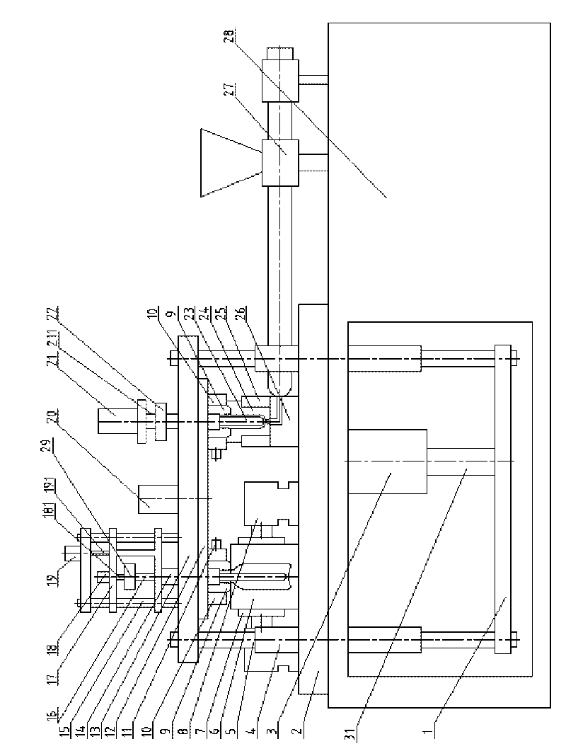
[0035]A double-station reciprocating rotary injection-stretch-blow molding machine includes two parts: a main machine and a mold. The main machine part includes a frame 28, a worktable panel 2 fixed horizontally on the frame 28, and placed The injection system 27 placed horizontally on the frame 28, the injection molding clamping system arranged perpendicular to the workbench panel 2, the blow molding mold clamping system placed horizontally on the workbench panel 2 and the stretching device arranged vertically;

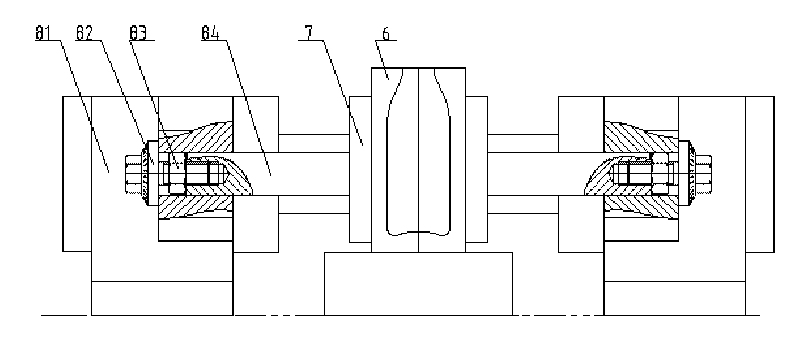
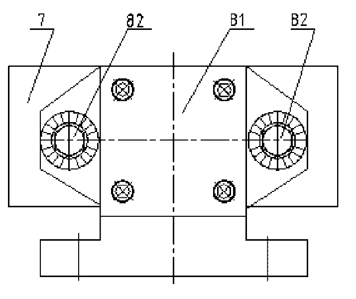
[0036] The injection molding clamping system includes an upper template 13, a workbench panel 2, a lower template 1, a clamping cylinder 3, a guide post 5, a rotary drive mechanism 20, a rotating disc 12 and a core pulling cylinder 21, and the workbench panel 2 is fixed horizontally On the frame 28, the lower formwork 1 is connected with the upper formwork 13 through four guide pillars 5 vertically passing through the workbench panel, the clamping oil cylinder 3 is fi...


PUM


Abstract

The invention discloses a double-station reciprocating rotary type injection stretch blow hollow forming machine which comprises a host machine and a mould. The host machine comprises a machine frame, a worktable panel, an injecting system, an injection molding and mould locking system, a blow molding and mould closing system, and a stretching device; wherein, the worktable panel is horizontally fixed on the machine frame, the injecting system is horizontally arranged on the machine frame, the injection molding and mould locking system is vertical to the worktable panel, the blow molding and mould closing system is horizontally arranged on the worktable panel, and the stretching device is vertically arranged. The injection molding and mould locking system comprises an upper mould plate, a lower mould plate, a mould locking oil cylinder, a guide post, a rotary driving mechanism, a rotary disc and a core-pumping oil cylinder. The lower mould plate is connected with the upper mould plate by the guide post which vertically penetrates through the worktable panel, the mould locking oil cylinder is fixed below the worktable panel, the piston rod end of the mould locking oil cylinder is connected with the lower mould plate, the rotary disc is arranged at the lower end face of the upper mould plate, and the rotary driving mechanism which is arranged at the upper part of the upper mould plate is connected with the rotary disc in a rotating manner. The rotary disc is driven by the rotary driving mechanism to drive a mouth module I and a mouth module II to carry out reciprocating rotation at 180 degrees in an interval manner, so as to finish station exchanging between blank injection and stretching blow molding, thereby realizing that the two functions of blank injection and stretching blow molding can be finished at the same time.

Description

【Technical field】 [0001] The invention relates to an injection stretch blow plastic bottle manufacturing equipment, in particular to a double station reciprocating rotary injection stretch blow hollow molding machine. 【Background technique】 [0002] At present, the processing of one-step injection stretch-blow plastic hollow containers at home and abroad mostly adopts three-station or four-station injection-stretch-blow hollow molding machines. Processing and assembly precision requirements are high, which will inevitably increase the manufacturing cost of the host machine and the mold and the production cost of the product. The invention patent "two-station one-step rotary injection stretch-blow molding machine" with the authorized notification number CN2649318Y improves the traditional "three-station" and "four-station" injection-stretch-blow blow molding machines, and adopts a two-station The scheme basically overcomes the problems of high manufacturing cost of the host ...

Claims


Application Information

Patent Timeline
Patent Type & Authority Applications(China)
IPC IPC(8): B29C49/06B29C49/56B29C49/48B29C49/12B29C49/42B29L22/00
Inventor 文炳荣文澜李晖周常凯温庆元梁家炳
Owner 柳州市精业机器有限公司
Why Eureka
Try Eureka