A tool for detecting interference phenomenon in the assembly of a hollow blade cooling duct and a manufacturing method

A technology for cooling ducts and testing tools, which is used in measuring devices, engine testing, and machine/structural component testing. , the effect of cost saving

Active Publication Date: 2021-01-05
SHENYANG LIMING AERO-ENGINE GROUP CORPORATION
View PDF7 Cites 0 Cited by
  • Summary
  • Abstract
  • Description
  • Claims
  • Application Information

AI Technical Summary

Problems solved by technology

[0003] However, both the cooling duct installed inside the blade and the surface of the inner cavity of the blade have complex spatial surface properties, and after the two are assembled, they also need to have a matching clearance requirement
[0004] Since the inner cavity of the blade is generally formed by casting, and a certain shape deviation is allowed, some blades will interfere when installing the cold air duct, so that the installed cooling duct is stuck in the inner cavity of the blade. At this time, the surface of the inner cavity of the blade needs to be repaired, and then the cooling duct can be assembled again. When the duct that has been stuck in the inner cavity of the blade is taken out, because the cooling duct is a hollow and thin-walled structure, resulting in A considerable number of cooling ducts are deformed and damaged when taken out, and these deformed and damaged cooling ducts will also become waste products
[0005] Therefore, the number of matching cooling ducts is about 20% more than the number actually assembled on the blade, resulting in additional cost expenditures

Method used


Image

  • A tool for detecting interference phenomenon in the assembly of a hollow blade cooling duct and a manufacturing method
  • A tool for detecting interference phenomenon in the assembly of a hollow blade cooling duct and a manufacturing method
  • A tool for detecting interference phenomenon in the assembly of a hollow blade cooling duct and a manufacturing method

Examples


Embodiment Construction

[0020] The present invention will be further described in detail below in conjunction with the accompanying drawings and specific embodiments.

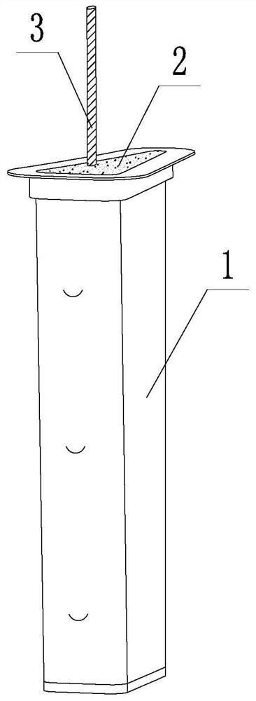
[0021] Such as figure 1 As shown, a hollow blade cooling duct assembly interference detection tool includes a cooling duct finished product 1, a duct lumen support body 2 and a handle 3; the inner cavity of the cooling duct finished product 1 is completely filled by the duct lumen support body 2 One end of the handle 3 is fixed in the support body 2 of the catheter lumen, and the other end of the handle 3 extends to the outside of the finished cooling catheter 1 .

[0022] The manufacturing method of the hollow blade cooling duct assembly interference phenomenon detection tool includes the following steps:

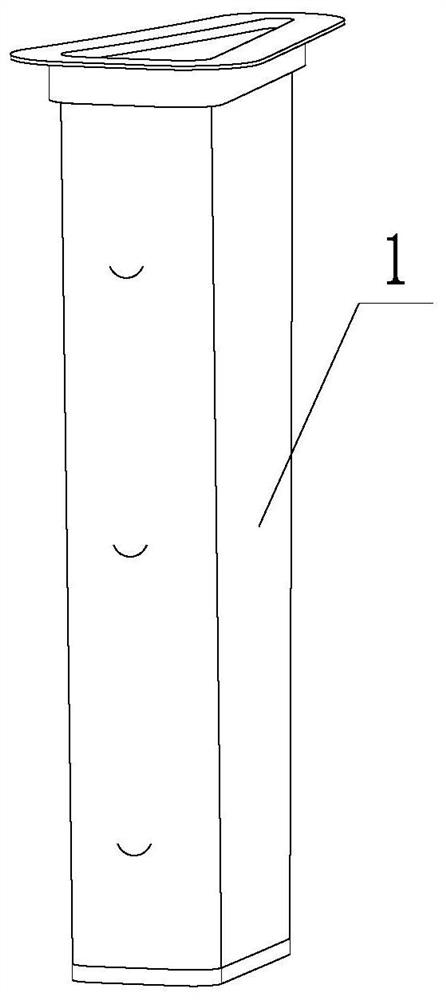
[0023] Step 1: Select a cooling duct product 1, such as figure 2 shown;

[0024] Step 2: Select the catheter lumen support body 2 used to fill the inner cavity of the finished product 1 of the cooling catheter. In this embodim...


PUM


Abstract

The invention discloses a hollow blade cooling guide pipe assembly interference phenomenon detection tool and a manufacturing method. The detection tool comprises a cooling guide pipe finished product, a guide pipe inner cavity supporting body and a handle. An inner cavity of the cooling guide pipe finished product is completely filled with the guide pipe inner cavity supporting body, one end of the handle is fixed in the guide pipe inner cavity supporting body, and the other end of the handle is extended out of the cooling guide pipe finished product. The manufacturing method of the detectiontool comprises the steps that one cooling guide pipe finished product is selected; the guide pipe inner cavity supporting body used for filling an inner cavity of the cooling guide pipe finished product is selected, the initial state of the guide pipe inner cavity supporting body is a liquid state, the guide pipe inner cavity supporting body in the liquid state is poured into the inner cavity ofthe cooling guide pipe finished product, a rigid rod is selected as the handle, one end of the handle is inserted into the guide pipe inner cavity supporting body, and the other end of the handle is left outside the cooling guide pipe finished product. On indoor temperature or heating conditions, the guide pipe inner cavity supporting body in the inner cavity of the cooling guide pipe finished product is gradually solidified till being completely in a solidified state, and manufacturing of the detection tool is finished.

Description

technical field [0001] The invention belongs to the technical field of manufacturing aero-engine parts, and in particular relates to a tool for detecting assembly interference phenomenon of a cooling duct of a hollow blade and a manufacturing method thereof. Background technique [0002] The reason why aero-engines use hollow air-cooled turbine guide blades is to make cooling air flow out from the air film holes evenly on the surface of the blade. Generally, a cooling duct is installed in the inner cavity of the blade so that the air inside the blade can flow freely. The air in the inner cavity of the blade is buffered, and the pressure is balanced before it flows out from the numerous air film holes on the surface of the blade. [0003] However, both the cooling duct installed inside the blade and the surface of the inner cavity of the blade have complex spatial curved surface properties, and after the two are assembled, they also need to have a matching clearance requireme...

Claims


Application Information

Patent Timeline
Patent Type & Authority Patents(China)
IPC IPC(8): F01D9/04F01D25/12G01M15/00
CPCF01D9/041F01D25/12G01M15/00
Inventor 刘随建贾爽梁巧云张平
Owner SHENYANG LIMING AERO-ENGINE GROUP CORPORATION
Why Eureka
Try Eureka