Chemical mechanical lapping device and system

A chemical machinery and grinding device technology, which is applied to grinding devices, abrasive surface adjustment devices, grinding machine tools, etc., can solve the problems that the stability of the polishing disc 14 is difficult to control, affect the uniform distribution of the grinding liquid, and the polishing disc 14 is cumbersome, etc. Slurry, easy to move, cost reduction effect

Active Publication Date: 2013-05-15
SEMICON MFG INT (SHANGHAI) CORP
View PDF10 Cites 22 Cited by
  • Summary
  • Abstract
  • Description
  • Claims
  • Application Information

AI Technical Summary

Problems solved by technology

[0006] 1) The polishing disc 14 is relatively large and takes up a lot of space, and the polishing disc 14 is relatively heavy and difficult to move;
[0007] 2) The layout of the whole grinding machine is very large, and the production cost is high;
[0008] 3) Since the polishing disc 14 is relatively large, the stability of the polishing disc 14 during rotation is difficult to control;
[0009] 4) The grinding fluid 18 needs to be distributed on the grinding pad with an area larger than the wafer, which not only wastes the grinding fluid, but also affects the uniform distribution of the grinding fluid

Method used


Image

  • Chemical mechanical lapping device and system
  • Chemical mechanical lapping device and system
  • Chemical mechanical lapping device and system

Examples


Embodiment 1

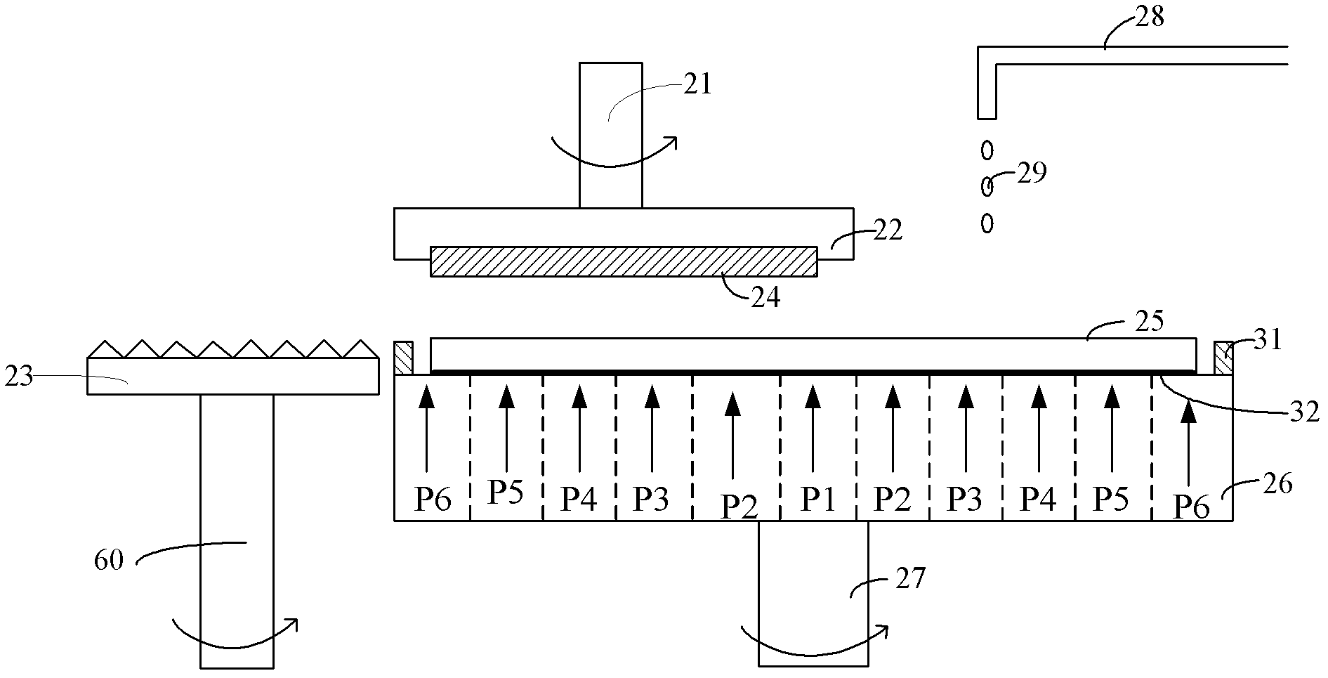
[0059] combined reference image 3 and Figure 4 , the present embodiment provides a chemical mechanical polishing device, comprising:

[0060] A wafer support seat 26 is used to support the wafer 25 to be ground, and the surface to be ground of the wafer 25 is upward;

[0061] Grinding pad 24, is arranged on the top of described wafer supporting seat 26, and the grinding surface of described grinding pad 24 is downward and is opposite to the surface to be polished of described wafer 25, and the area of ​​the grinding surface of described grinding pad 24 is smaller than described The area of ​​the surface to be ground of the wafer 25;

[0062] The grinding pad fixing part 22 is arranged above the grinding pad 24 for fixing the grinding pad 24;

[0063] The shaft 21 is arranged above the polishing pad fixing part 22, and is used to drive the polishing pad fixing part 22 and the polishing pad 24 to rotate;

[0064] The raw material supply device 28 is arranged above the wafe...

Embodiment 2

[0083] refer to Figure 5 As shown, this embodiment provides a chemical mechanical grinding device, which is different from Embodiment 1 in that the raw material supply device is different.

[0084] The raw material supply device in this embodiment may include: a bearing cylinder 53 fixed on the upper surface of the grinding pad fixture 22; a grinding fluid supply pipe 48 arranged above the bearing cylinder 53 for supplying grinding fluid 29 ; the polishing pad fixing part 22 and the polishing pad 24 are provided with a plurality of through holes 50 passing through the polishing pad fixing part 22 and the polishing pad 24 .

[0085] In this embodiment, the grinding liquid 29 only needs to be sprayed on the grinding pad 24 , thereby further saving the grinding liquid 29 and further improving the uniformity of the distribution of the grinding liquid 29 .

[0086] Wherein, the carrying cylinder 53 may be a hollow cylinder with upper and lower openings.

[0087] Specifically, th...


PUM


Abstract

The invention provides a chemical mechanical lapping device and a system. The chemical mechanical lapping device comprises a wafer supporting seat, a lapping pad, a lapping pad fixed piece, a shaft lever and a raw material providing device, wherein the wafer supporting seat is used for supporting a wafer to be lapped, and a surface to be lapped of the wafer is upward, the lapping pad is arranged on the upper part of the wafer supporting seat, a lapping surface of the lapping pad is downward and is opposite to the surface to be lapped of the wafer, the area of the lapping area of the lapping pad is less than the area of the surface to be lapped of the wafer, the lapping pad fixed piece is fixed on the upper portion of the lapping pad and for fixing the lapping pad, the shaft lever is arranged on the upper part of the lapping pad fixed piece and for driving the lapping pad fixed piece and the the lapping pad to rotate, and the raw material providing device is arranged on the upper part of the wafer supporting seat for providing lapping liquids for the surface to be lapped of the wafer. According to the chemical mechanical lapping device and the system, wafers with diameters of 450mm or more can be lapped simply and accurately.

Description

technical field [0001] The invention relates to the technical field of semiconductors, in particular to a chemical mechanical polishing device and system. Background technique [0002] The Chemical Mechanical Planarization (CMP) process is a planarization process. Since it was introduced into the integrated circuit manufacturing process in 1990, after continuous practice and development, it has become a key process to promote the continuous shrinking of the integrated circuit technology node. At present, CMP has been widely used in shallow trench isolation structure planarization, gate electrode planarization, tungsten plug planarization, copper interconnection planarization and other processes. The CMP process is also applied to remove thin film layers on the surface of the substrate. [0003] For related technologies of CMP, reference may be made to US Patent No. US5722875, which discloses a polishing method and apparatus (method and appartus for polishing). [0004] fi...

Claims


Application Information

Patent Timeline
Patent Type & Authority Applications(China)
IPC IPC(8): B24B37/10B24B37/26B24B37/34B24B53/017H01L21/67
Inventor 陈枫周梅生
Owner SEMICON MFG INT (SHANGHAI) CORP
Why Eureka
Try Eureka