U-shaped steel-concrete composite beam

A U-shaped steel and concrete technology, which is applied in the direction of load-bearing elongated structural components, structural elements, building components, etc., can solve the problem that it is difficult to ensure that steel beams and concrete work together completely, low shear bearing capacity, and overall stability Poor performance and other problems, to achieve the effect of simplifying the construction process, high shear bearing capacity, and reducing the overall manufacturing cost

Active Publication Date: 2014-06-04
JIANGSU ZHONGBAO STEEL STRUCTURE
View PDF8 Cites 15 Cited by
  • Summary
  • Abstract
  • Description
  • Claims
  • Application Information

AI Technical Summary

Problems solved by technology

[0004] The invention aims to solve the problems of poor fire resistance and poor overall stability of the existing I-shaped steel-concrete composite beams, and the low shear bearing capacity of the composite steel-concrete laminated beams, making it difficult to ensure that the steel beams and concrete work together completely. And then provide a kind of U-shaped steel-concrete composite beam

Method used


Image

  • U-shaped steel-concrete composite beam
  • U-shaped steel-concrete composite beam

Examples


specific Embodiment approach 1

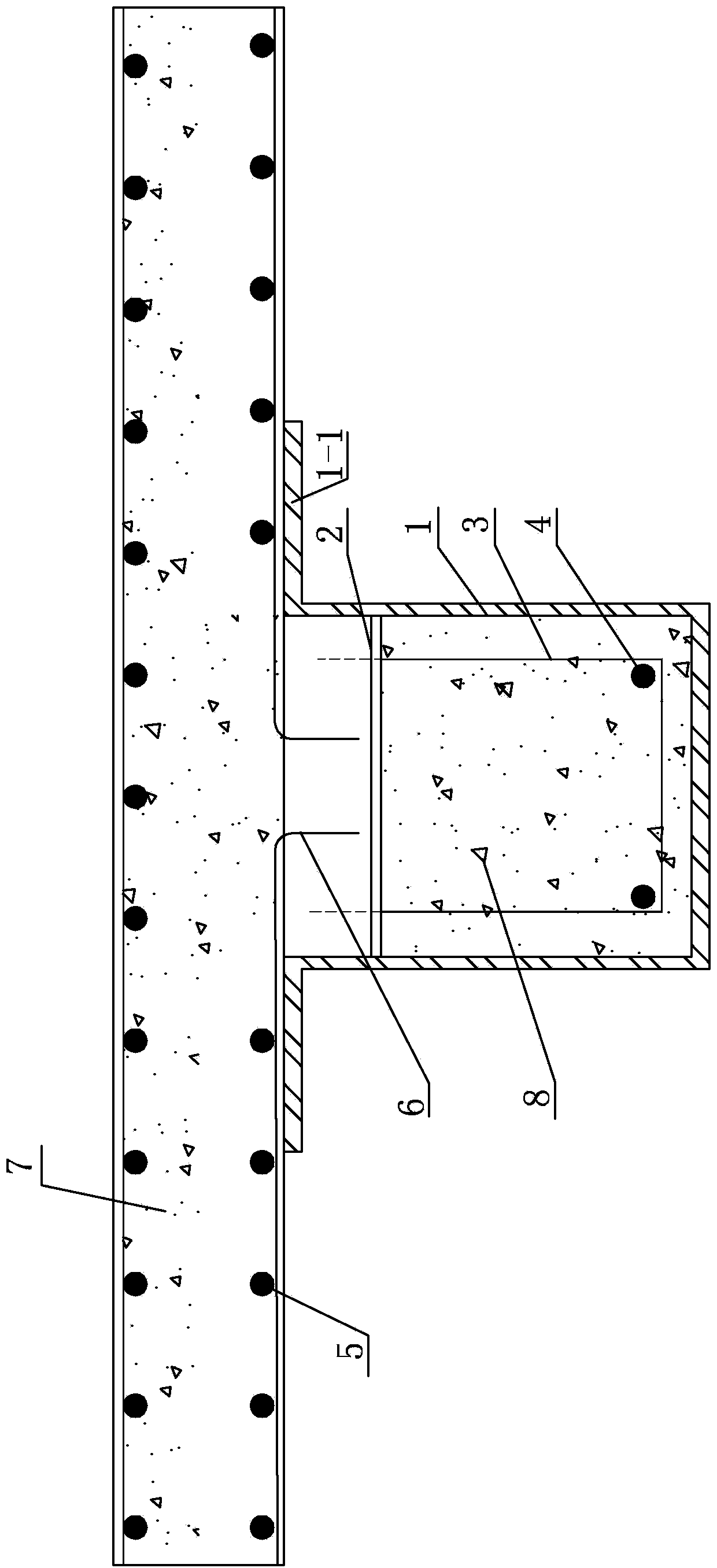
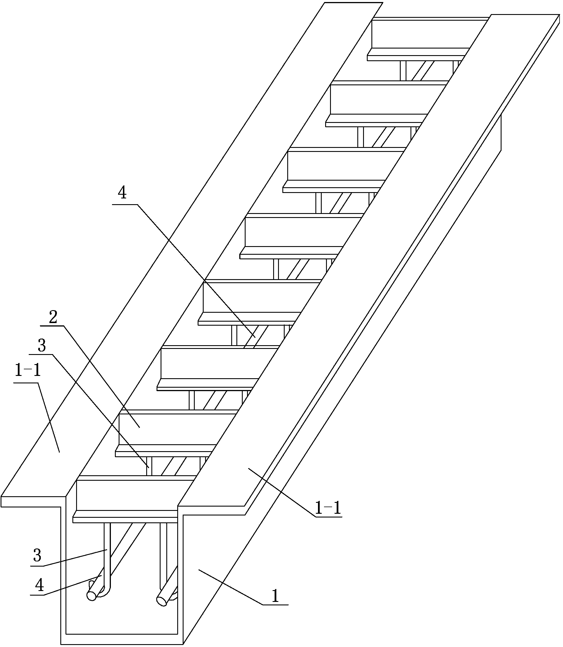
[0009] Specific implementation mode one: combine Figure 1-Figure 2 Explain that a U-shaped steel-concrete composite beam in this embodiment includes a concrete slab 7, which also includes a U-shaped steel 1, a plurality of angle steels 2, a plurality of longitudinally stressed reinforcement bars 4, a plurality of erection reinforcement bars 3 and concrete 8 ;

[0010] The upper end of each web plate of the U-shaped steel 1 is fixedly connected with a horizontally arranged flange plate 1-1, and the U-shaped steel 1 and the flange plate 1-1 are integrally made, and the inside of the U-shaped steel 1 is fixedly connected along its length direction. A plurality of angle steels 2, the length direction of the angle steel 2 is perpendicular to the length direction of the U-shaped steel 1, and a plurality of longitudinally stressed steel bars 4 are arranged at intervals along the length direction of the U-shaped steel 1, and a vertical steel bar is welded on the side of each angle st...

specific Embodiment approach 2

[0012] Specific implementation mode two: combination figure 2 Illustrate, the erecting reinforcing bar 3 of the present embodiment adopts U-shaped reinforcing bar or erecting reinforcing bar with crotch hook, and the longitudinal stressed reinforcing bar 4 is affixed to the U-shaped groove or the bend of erecting reinforcing bar 3 along the length direction of U-shaped steel 1. inside the hook. With such arrangement, the structure forms are various, and the connection is stable and reliable. Others are the same as in the first embodiment.

specific Embodiment approach 3

[0013] Specific implementation mode three: combination figure 2 To illustrate, the U-shaped steel 1 and the angle steel 2 in this embodiment are connected by welding. With such arrangement, the angle steel can be arranged inside the U-shaped steel or placed on the top surface of the U-shaped steel, the structure is simple, and the force transmission is direct and simple. Others are the same as in the first or second embodiment.


PUM


Abstract

The invention discloses a U-shaped steel-concrete composite beam, relates to a composite beam, and solves the problems that the conventional I-shaped steel-concrete composite beam has poor fire resistance and poor overall stability, an outsourcing steel-concrete laminated plate composite beam has low anti-shear bearing capacity, the complete cooperative work of a steel beam and concrete is not guaranteed easily. The U-shaped steel-concrete composite beam comprises a concrete plate, U-shaped steel, a plurality of pieces of angle steel, a plurality of longitudinal stress reinforcing steel bars, a plurality of erect reinforcing steel bars and the concrete; each web plate of the U-shaped steel is fixedly connected with a flange plate which is arranged horizontally; the U-shaped steel and the flange plate are integrated; the plurality of pieces of angle steel are fixedly connected in the U-shaped steel along the length direction of the U-shaped steel; an erect reinforcing steel bar is welded on the side surface of each piece of angle steel; the longitudinal stress reinforcing steel bars are fixedly connected with the corresponding erect reinforcing steel bars along the length direction of the U-shaped steel; the concrete plate is arranged on the top of the U-shaped steel; the reinforcing steel bars in the concrete plate are bent and then extend into the U-shaped steel; the concrete is cast in the U-shaped steel. The U-shaped steel-concrete composite beam is applied to civil engineering construction.

Description

technical field [0001] The invention relates to a composite beam, in particular to a U-shaped steel-concrete composite beam without fireproof paint, and belongs to the technical field of building structures. Background technique [0002] The steel-concrete composite beam has the advantages of high rigidity and high bearing capacity, and has been widely used in practical engineering. At present, the I-shaped steel-concrete composite beam is commonly used in engineering. The I-shaped steel-concrete composite beam is directly exposed because the steel beam is directly exposed. In actual engineering, it is necessary to apply fireproof coatings on the I-shaped steel to improve the fire resistance of the composite beam, resulting in an increase in the cost of the I-shaped steel-concrete composite beam; at the same time, the I-shaped steel-concrete composite beam bears In the bending moment zone, the lower flange of the steel beam is under compression. In order to prevent the plane...

Claims


Application Information

Patent Timeline
Patent Type & Authority Applications(China)
IPC IPC(8): E04C3/293
Inventor 郭兰慧周国平
Owner JIANGSU ZHONGBAO STEEL STRUCTURE
Why Eureka
Try Eureka