Capacity adjustable vortex compressor refrigeration system with mediate loop installed with ejector

A technology of scroll compressors and intermediate circuits, applied in the direction of irreversible cycle compressors, compressors, refrigerators, etc., to achieve the effects of improving adaptability, reducing power consumption, and simplifying design and control

Inactive Publication Date: 2008-04-30
TSINGHUA UNIV
View PDF0 Cites 14 Cited by
  • Summary
  • Abstract
  • Description
  • Claims
  • Application Information

AI Technical Summary

Problems solved by technology

Therefore, the measures of setting the connection port of the discharge pipe and the low pressure side at the front or rear of the evaporator have their own advantages and disadvantages

Method used


Image

  • Capacity adjustable vortex compressor refrigeration system with mediate loop installed with ejector
  • Capacity adjustable vortex compressor refrigeration system with mediate loop installed with ejector

Examples


Embodiment 1

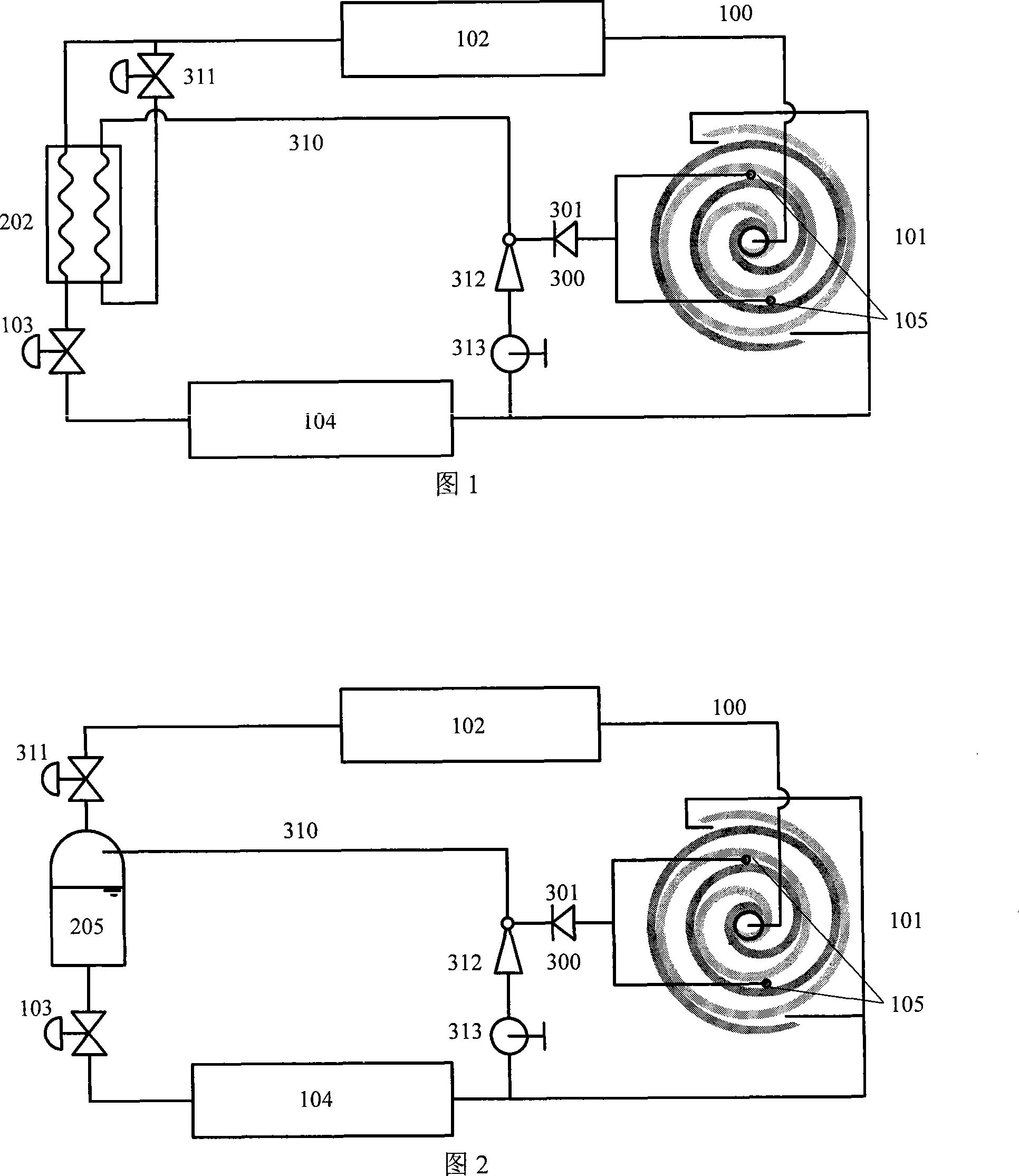
[0027] FIG. 1 is a schematic structural diagram of a scroll compressor refrigeration system using an ejector and an intermediate heat exchanger for refrigerant discharge.

[0028] The system includes a refrigerant main circuit 100 and a refrigerant discharge system. The refrigerant main circuit 100 is formed by sequentially connecting a scroll compressor 101 with a refrigerant outlet 105 , a condenser 102 , a system expansion device 103 and an evaporator 104 . The refrigerant discharge system includes an intermediate heat exchanger 202, a refrigerant discharge working circuit 310 and a refrigerant refrigeration discharge ejection circuit 300, wherein the intermediate heat exchanger 202 is arranged on the main refrigerant circuit 100 of the system from the condenser 102 to the On the pipeline between the expansion devices 103 of the system, one end of the refrigerant discharge working circuit 310 is connected to the outlet pipeline of the condenser 102, and the other end passes...

Embodiment 2

[0032] FIG. 2 is a schematic structural diagram of a scroll compressor refrigeration system using an ejector and a flash tank for refrigerant discharge. The system includes a refrigerant main circuit 100 and a refrigerant discharge system. The refrigerant main circuit 100 is formed by sequentially connecting a scroll compressor 101 with a refrigerant outlet 105 , a condenser 102 , a system expansion device 103 and an evaporator 104 . The refrigerant discharge system includes a discharge expansion device 311, a flash tank 205, a refrigerant discharge working circuit 310 and a refrigerant refrigeration discharge ejection circuit 300, wherein the discharge expansion device 311 and the flash tank 205 are sequentially arranged in On the main refrigerant circuit 100 of the system, on the pipeline from the outlet of the condenser 102 to the inlet of the expansion device 103 of the system, one end of the refrigerant discharge working circuit 310 is connected to the flash tank 205, and...

Embodiment 3

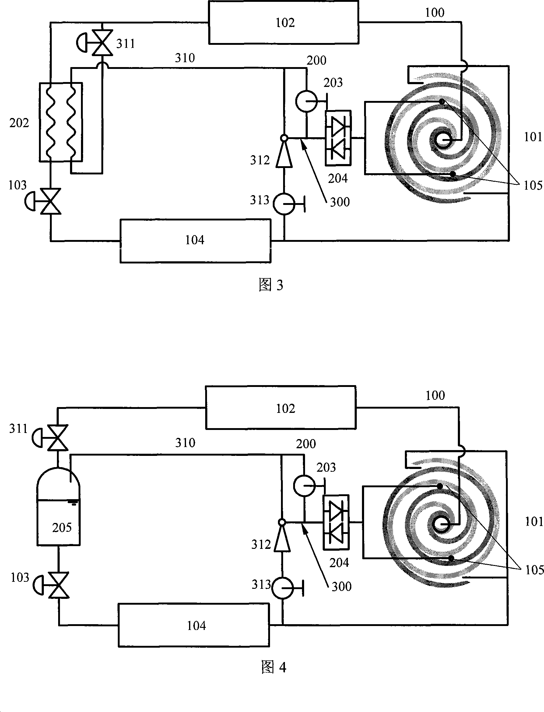
[0036]3 is a schematic structural diagram of a scroll compressor refrigeration system using an ejector and an intermediate heat exchanger for refrigerant discharge and injection. The system includes a refrigerant main circuit 100 , a refrigerant discharge system and a refrigerant injection circuit 200 . The refrigerant main circuit 100 is formed by sequentially connecting a scroll compressor 101 with a refrigerant outlet 105 , a condenser 102 , a system expansion device 103 and an evaporator 104 . The refrigerant discharge system includes an intermediate heat exchanger 202, a refrigerant discharge working circuit 310 and a refrigerant refrigeration discharge ejection circuit 300, wherein the intermediate heat exchanger 202 is arranged on the main refrigerant circuit 100 of the system from the condenser 102 to the On the pipeline between the expansion devices 103 of the system, one end of the refrigerant discharge working circuit 310 is connected to the outlet pipeline of the c...


PUM


Abstract

The invention relates to a capability adjustable volution compressor refrigerating system with a jet apparatus arranged on a central loop, and belongs to the refrigerating and air-condition field. A central pressure loop is arranged between an exit of a condenser and an entrance of a compressor, the top of the loop is provided with a jet apparatus, the invention uses the jet apparatus to lead and shoot the refrigerating fluid discharged from the compressed central section toward the low pressure side by utilizing the pressure difference between the central pressure loop and the inhaling mouth of the compressor, thereby strengthening the discharging function of the system refrigeration fluid and elevating the unloading ability of the volution compressor. Simultaneously, the combination of the strengthened refrigerating fluid discharging technique and the refrigerating fluid ejecting technique greatly elevates the capability changing ability toward the two directions of big and small of the volution compressor refrigerating system. The technique can be used for the refrigeration/heating pump system in the air-condition refrigeration field containing the volution compressor, can effectively change the efficiency, system capability and capacity of the compressor, and make the system work with high efficiency in a much bigger working condition range, thereby elevate the applicability under the condition of the working condition changing in a bigger range of the system.

Description

technical field [0001] The invention relates to a refrigeration system containing a scroll compressor, belonging to the field of refrigeration and air conditioning. More specifically, it relates to a system form and a control method for changing the capacity and performance of a refrigeration system containing a scroll compressor through refrigerant leakage or / and injection. Background technique [0002] A scroll compressor is a type of compressor for refrigeration and air conditioning. Due to the advantages of high efficiency and low noise, scroll compressors are widely used in small and medium capacity refrigeration and air conditioning systems. The scroll compressor has a pair of symmetrically arranged scroll discs (static disc and moving disc). In the initial stage of compression, the low-pressure refrigerant gas is drawn into the compression chamber by the outer side wall of the scroll, and then enclosed in the compression chamber with the translation of the scroll. ...

Claims


Application Information

Patent Timeline
Patent Type & Authority Applications(China)
IPC IPC(8): F25B1/04F25B9/08F25B41/00
CPCF25B2400/23F25B2400/13F25B1/04F25B2341/0011
Inventor 王宝龙石文星李先庭韩林俊
Owner TSINGHUA UNIV
Why Eureka
Try Eureka