Pulse excited double steady-state electromagnetic actuator

An actuator and steady-state technology, applied in the direction of electromagnets, protection switch operation/release mechanisms, etc., can solve problems such as inconvenient use, high requirements for iron core materials, and complex structures

Inactive Publication Date: 2005-03-30
HUNAN AOMENG ELECTRIC
View PDF3 Cites 13 Cited by
  • Summary
  • Abstract
  • Description
  • Claims
  • Application Information

AI Technical Summary

Problems solved by technology

However, its iron core material requirements are high, its structure and control system are complex, and positive and negative power supplies are required, so it is expensive and inconvenient to use, which limits its popular use.
Type III uses instantaneous unidirectio

Method used


Image

  • Pulse excited double steady-state electromagnetic actuator
  • Pulse excited double steady-state electromagnetic actuator
  • Pulse excited double steady-state electromagnetic actuator

Examples


Embodiment 1

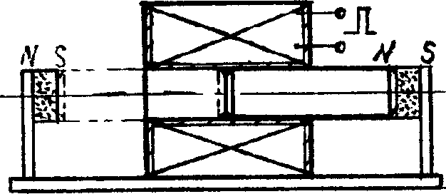
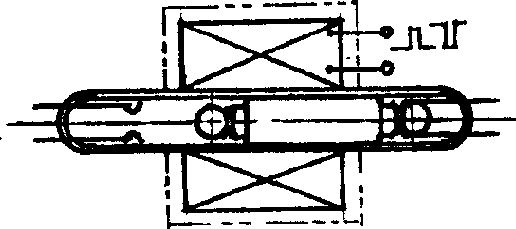
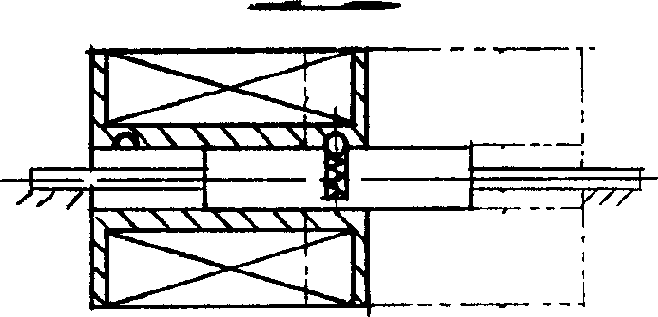
[0048] Embodiment 1, the microcoil type fully sealed contact bistable relay that the present invention forms, as figure 2 As shown, the two ends of the glass tube are sealed with elastic reeds bent into the shape of sockets as electrical contacts and steady state maintenance devices. The two ends of the electromagnet core made of soft magnetic materials are processed into plug shapes, and after surface treatment such as electroplating Put it into the tube as moving parts and moving contacts, and the middle part outside the tube is wound with a winding whose width is less than the length of the iron core. Adding a pulse current in any direction with appropriate width to the winding can make the iron core move between the two sets of contacts and make it close or break. In order to reduce the reluctance, the outer magnetic circuit core can also be added outside the winding, as shown by the double dotted line in the figure. If the fit between the iron core and the tube wall is ...

Embodiment 2

[0049] Embodiment 2, the rotary armature type bistable actuator constituted by the present invention can be used in facilities such as ball valves, load switches, circuit breakers, and rotary electromagnets. Such as Figure 7 As shown, in a circular stator core with two protruding magnetic poles, four magnets are concentrically arranged in pairs, and the magnetic poles of each pair are different. A two-pole rotor with windings can rotate around the central axis and swing on both sides of the stator poles. When the rotor is at two stable points, the two poles correspond to the magnetic poles of a pair of magnets. There is also an elastic positioning block in the stator to limit the position of the rotor at two stable points, so that it is slightly deviated from the center line of the magnet in the direction of the stator pole. After the rotor is excited, its pulse magnetic pole should be the same as that of the two corresponding magnets, so that the rotor will move towards the...

Embodiment 3

[0050] Embodiment 3, the swing type micropipe fully sealed contact bistable relay that the present invention forms, as Figure 9 As shown, a magnetic pole made of conductive soft magnetic material is encapsulated at one end of the glass tube, and a conductive soft magnetic swing rod is hinged inside the tube (the swing rod can also be hinged at the center of gravity so that it is not affected by gravity), and the other end of the glass tube is encapsulated in the middle There is a magnetic pole of soft magnetic material, and a contact piece made of conductive soft magnetic material is packaged on both sides. The outer roots of the two contact piece tubes are respectively pasted with small magnetic pieces of the same polarity, so that the inner ends of the tube have the same magnetic pole and can attract the pendulum. The end of the rod keeps it in a steady state, (the two contact pieces can also be directly formed by conductive permanent magnet materials), and the winding is ou...


PUM


Abstract

The disclosed actuator is applicable to relay, contactor, breaker, solenoid valve and electromagnet etc. Stable state is maintained through excitated actuation by pulse current, magnet, or snap spring, spring catch and spring etc. Thus, bi-directional pulse generating circuit, winding changing switch in prior art, or complicated bistable mechanism and spring of reverberatory force can be omitted, only one switch with unidirectional pulse being input is adopted so as to possess features of energy saving, antivibration, simple structure, easy of miniaturization, unease of wobble and long working travel. The actuator includes base, electromagnet and stable maintaining unit. Two stable places are located at two sides of action spot of largest magnetic attraction. Movable piece at one stable place can be changed to another stable place by pulse magnetic force of electric magnet.

Description

technology field; [0001] The invention relates to a pulse excitation bistable electromagnetic actuator used in the field of electromagnetic actuators such as relays, contactors, circuit breakers, electromagnetic valves, and electromagnets. Background technique; [0002] At present, there are roughly three types of bistable electromagnetic actuators used in the above fields: I, electromagnet plus armature type <continuous power supply excitation actuation and holding>; II, electromagnet plus permanent magnet or torque core plus armature type (positive and negative bidirectional pulse current excitation actuation, permanent magnet or residual magnetism hold), such as Chinese patent application 98100891.7 (CN1192035A, 98-9-2); III, electromagnet plus mechanical bistable mechanism plus armature type <single Actuated by pulse current excitation, mechanical bistability >, see Chinese patent application 89206214.2 (CN2052949u, 90-2-14), 91107223.3 (CN1067768A, 93-1-6). ...

Claims


Application Information

Patent Timeline
IPC IPC(8): H01F7/06H01H71/24H01H71/68
Inventor 孙奇锋孙奇敏孙天玲
Owner HUNAN AOMENG ELECTRIC
Why Eureka
Try Eureka