Bar pushing device

A technology for pushing devices and bars, which is applied in the direction of conveyor objects, transportation and packaging, etc., which can solve the problems of irregular movement of bars, inability to move forward, and accumulation of bars in the conveying channel, etc., to achieve a clear source of power Effect

Pending Publication Date: 2022-01-04
HANGZHOU ZHONGYA MACHINERY CO LTD
View PDF0 Cites 0 Cited by
  • Summary
  • Abstract
  • Description
  • Claims
  • Application Information

AI Technical Summary

Problems solved by technology

In the prior art, the circular vibrating rod unscrambling machine is often used to arrange the bar stock. The bar stock output on the circular vibrating bar unscrambler moves forward with the vibration rhythm, but is affected by the factors of each bar stock itself, so that the bar stock moves forward. The trend is irregular, and once it is hindered by a large frictional force, it cannot move forward
Therefore, in the prior art, the power for bar movement comes from the circular vibrating bar unscrambler, but the power that can drive the bar forward is relatively small, the conveying process of the bar is uncontrollable, and it is very easy for the bar to accumulate in the conveying channel

Method used


Image

  • Bar pushing device
  • Bar pushing device
  • Bar pushing device

Examples


Embodiment Construction

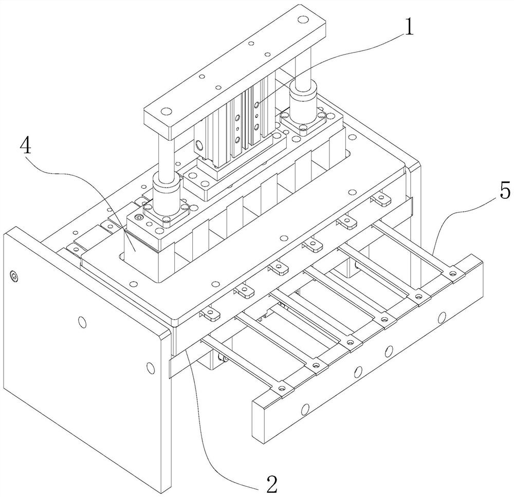
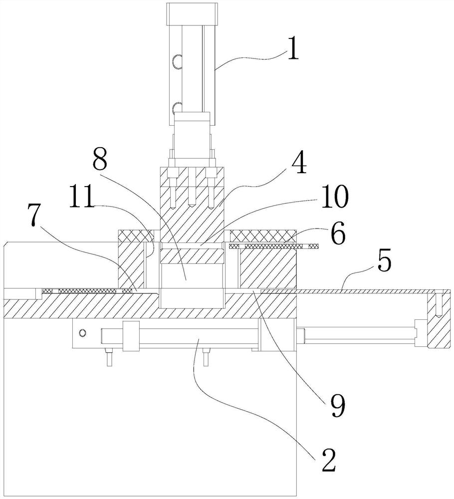
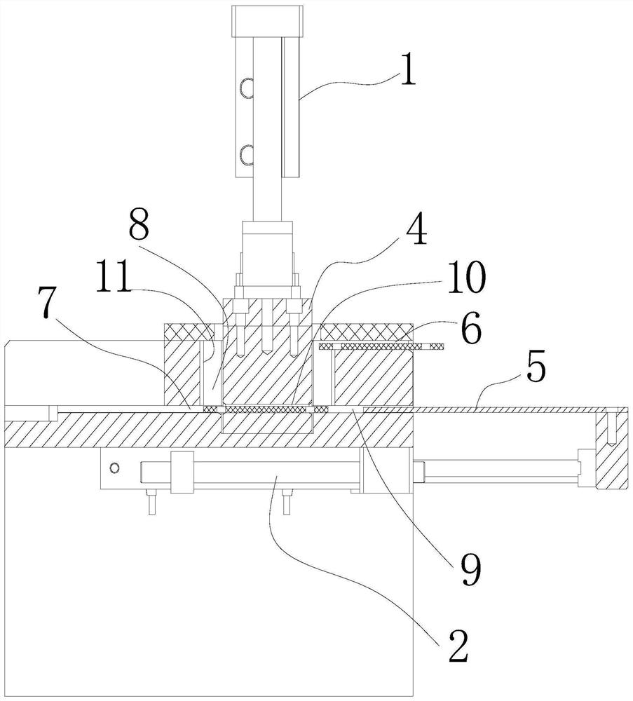
[0012] Such as figure 1 , 2 , 3, the bar pushing device includes a lifting cylinder 1, a horizontal pushing cylinder 2, a base 3, a connecting piece 4, and a bar pushing plate 5. The base 3 is provided with a feed channel 6 , a discharge channel 7 , a working channel 8 and a guide channel 9 . The working channel 8 is vertically arranged, and the base 3 is an open structure at the top of the working channel 8 . The discharge channel 7 and the guide channel 9 are distributed on both sides of the working channel 8 and located at the bottom of the working channel 8, and the discharge channel 7 and the guiding channel 9 are on the same center line and are located in the same horizontal direction. The feeding channel 6 is located on one side of the working channel 8 and above the guiding channel 9 . The centerline of the feed channel 6 is parallel to the centerline of the outlet channel 7 . The feed channel 6 and the discharge channel 7 are distributed on both sides of the worki...


PUM


Abstract

The invention discloses a bar pushing device which comprises a lifting air cylinder, a horizontal pushing air cylinder, a base, a connecting piece and a bar pushing plate. A feeding channel and a discharging channel are arranged on the base, a connecting channel is arranged on the connecting piece, the connecting piece is installed on the base through the lifting air cylinder, the feeding channel and the discharging channel are distributed on the two sides of the connecting piece, the feeding channel, the discharging channel and the connecting channel are parallel to one another and are located in the same vertical plane, the feeding channel and the discharging channel are arranged in the vertical plane in a staggered mode, and the bar pushing plate is installed on the base through the horizontal pushing air cylinder. The discharging channel is located in the extending direction of the bar pushing plate, and the moving direction of the connecting piece on the base is perpendicular to the moving direction of the bar pushing plate on the base. The bar pushing device can receive bars which move disorderly and are output by a circular vibration bar arranging machine, stably and reliably drive each bar to move forwards through the connection function of the bar pushing device, and enables a power source of the bars to be clear, stable and sufficient in the conveying stage.

Description

technical field [0001] The invention relates to a bar pushing device. Background technique [0002] In the food industry, sticks are placed in the food body for easy handling. Common products include popsicles, cheese sticks, lollipops, oden, and semi-finished fried foods. Before the bar is inserted into the product, it exists in the handling link in a loose manner, and needs to be sorted and transported before use. In the prior art, the circular vibrating rod unscrambling machine is often used to arrange the bar stock. The bar stock output on the circular vibrating bar unscrambler moves forward with the vibration rhythm, but is affected by the factors of each bar stock itself, so that the bar stock moves forward. The trend is irregular, and once it is hindered by greater friction, it cannot move forward. Therefore, in the prior art, the power for bar movement comes from the circular vibrating bar unscrambler, but the power that can drive the bar forward is relatively smal...

Claims


Application Information

Patent Timeline
Patent Type & Authority Applications(China)
IPC IPC(8): B65G47/82B65G47/28
CPCB65G47/82B65G47/28
Inventor 史中伟史正樊杰飞
Owner HANGZHOU ZHONGYA MACHINERY CO LTD
Why Eureka
Try Eureka