Planar floating connecting device and application thereof

A technology of floating connection and planar movement, which is applied in the direction of fluid pressure actuators, thin plate connections, connecting components, etc. It can solve the problems of unusable connection, damage, failure to ensure the push rod and auxiliary push rod of the cylinder, and reduce production. Effects of manufacturing cost, avoidance of machining and assembly accuracy

Pending Publication Date: 2022-01-04
ZHEJIANG YUYAN IND DESIGN CO LTD
View PDF0 Cites 0 Cited by
  • Summary
  • Abstract
  • Description
  • Claims
  • Application Information

AI Technical Summary

Problems solved by technology

However, due to human factors or installation accuracy problems, it is impossible to ensure that the push rod of the cylinder and the auxiliary push rod are absolutely parallel. uneven and damaged
However, the floating joints currently on the market are based on the motion of the ball pair, and are mainly used for the connection of components with a certain degree of relative swing, that is, to adjust the deflection angle, but they cannot be used for two components with a certain degree of planar motion. the connection between

Method used


Image

  • Planar floating connecting device and application thereof
  • Planar floating connecting device and application thereof
  • Planar floating connecting device and application thereof

Examples


Embodiment

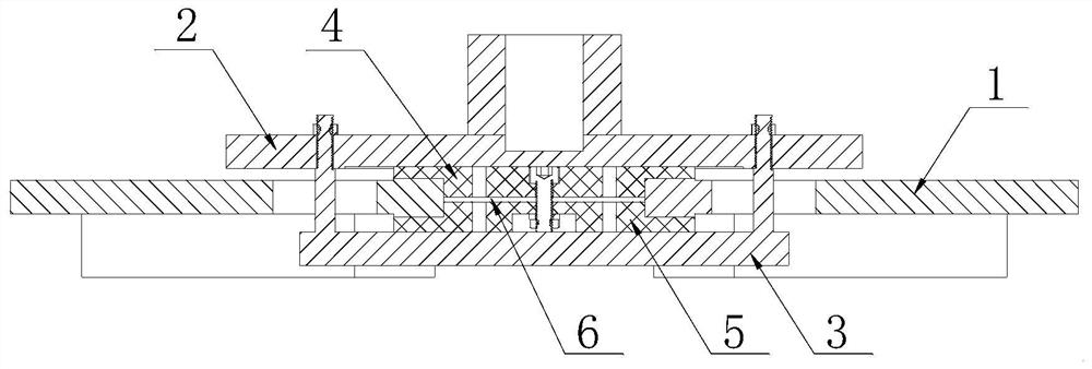
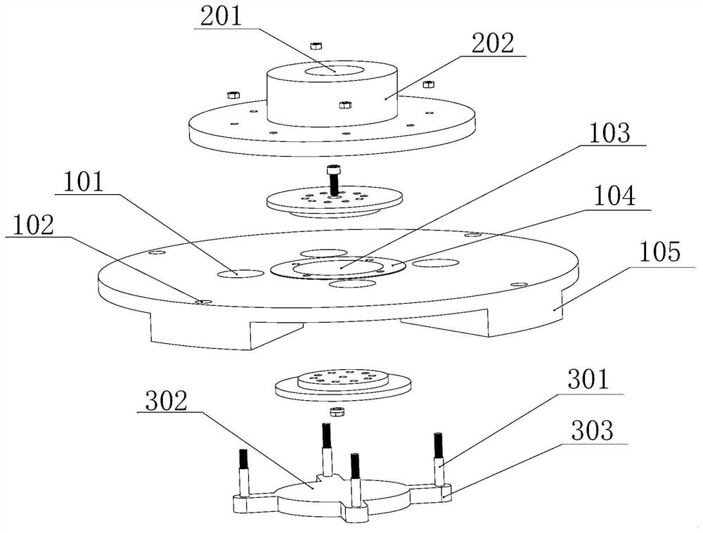
[0025] In this embodiment, the lower plate 3 includes a disc body 302 , on which a plurality of lugs 303 are arranged in the circumferential direction, and the connecting posts 301 are fixed on the lugs 303 . Further, the connecting column 301 is provided with external threads, and the connecting column 301 passes through the through hole on the upper sliding plate 2 and is fixed by a nut. At this time, the lower plate 3 has a simple structure, is convenient to manufacture, and is easy to assemble and fix. During installation, it is only necessary to pass the connecting column 301 through the limit hole 101 on the base plate 1 and the through hole on the upper sliding plate 2 in sequence, and then use the nut to cooperate with the external thread on the connecting column 301 to realize installation and fixing, and the operation is simple . (It is also possible to arrange the internal thread structure on the upper slide plate 2, and cooperate with the external thread on the co...


PUM


Abstract

The invention relates to a planar floating connecting device, which comprises a base plate, an upper sliding plate, a lower sliding plate, an upper sliding lining and a lower sliding lining; the upper sliding lining and the lower sliding lining are fixedly arranged on the two sides of the base plate and clamp the base plate; an upper sliding plate is arranged above the upper sliding lining and can do planar motion relative to the upper sliding lining; a lower sliding plate is arranged below the lower sliding lining and can do planar motion relative to the lower sliding lining; a plurality of connecting columns are arranged on the lower sliding plate, and correspondingly, a plurality of limiting holes are arranged on the base plate; the connecting columns penetrate through the limiting holes and are fixed to the upper sliding plate; and a blind hole matched with an air cylinder push rod for installation is arranged at the middle of the upper sliding plate, and a set of installation holes used for being connected with external components are arranged on the base plate in the circumferential direction. According to the planar floating connecting device provided by the invention, error adjustment in any direction between two components can be achieved in a small range, unnecessary machining and assembling precision is avoided, and the production and manufacturing cost is reduced. Correspondingly, the invention further provides air cylinder pushing equipment constructed by using the planar floating connecting device.

Description

technical field [0001] The invention relates to the technical field of floating connection, in particular to a planar floating connection device and its application. Background technique [0002] As a power actuator, the cylinder is mainly driven by compressed air, and its key component is the piston rod. In daily use, due to assembly errors, the piston rod and the moving components connected to it are inevitably out of concentricity, and the piston rod cannot be vertical. After the cylinder is used for a long time, the wear of the sealing ring will be accelerated, resulting in the piston The seal between the rod and the cylinder liner is damaged, which in turn damages the cylinder and affects the service life of the cylinder. The floating joint can be used to connect the cylinder and the corresponding moving components, and the connection between the piston rod of the cylinder and the moving components can be adjusted, so that the direction of the force and the point of fo...

Claims


Application Information

Patent Timeline
Patent Type & Authority Applications(China)
IPC IPC(8): F15B15/20F16B5/02F16N1/00
CPCF15B15/20F16B5/0225F16N1/00
Inventor 梅丽莎林泽舜
Owner ZHEJIANG YUYAN IND DESIGN CO LTD
Why Eureka
Try Eureka