
Unmanned aerial vehicle relay communication method based on virtual array antenna cooperative beam forming

A beamforming, virtual array technology, applied in the field of wireless networks, can solve problems such as damage, link failure, increased energy consumption, etc., to achieve the effect of increasing transmission rate and improving security performance

Active Publication Date: 2022-01-04
JILIN UNIV
View PDF9 Cites 3 Cited by
  • Summary
  • Abstract
  • Description
  • Claims
  • Application Information

AI Technical Summary

Problems solved by technology

The establishment of links between telecommunication access points can be achieved through single-hop or multi-hop methods, but this method may cause link failures and increase energy consumption. Known and unknown eavesdroppers try to intercept the data between the sending base station and the remote receiving base station and maliciously tamper or destroy it, which will lead to serious communication security problems
The confidential communication in the wireless network can be realized by adopting the upper-layer encryption method, but frequent encryption and decryption require high computing power, which brings severe challenges to UAVs with limited hardware resources.

Method used


Image

  • Unmanned aerial vehicle relay communication method based on virtual array antenna cooperative beam forming
  • Unmanned aerial vehicle relay communication method based on virtual array antenna cooperative beam forming
  • Unmanned aerial vehicle relay communication method based on virtual array antenna cooperative beam forming

Examples


Embodiment Construction

[0037] The present invention will be further described in detail below in conjunction with the accompanying drawings, so that those skilled in the art can implement it with reference to the description.

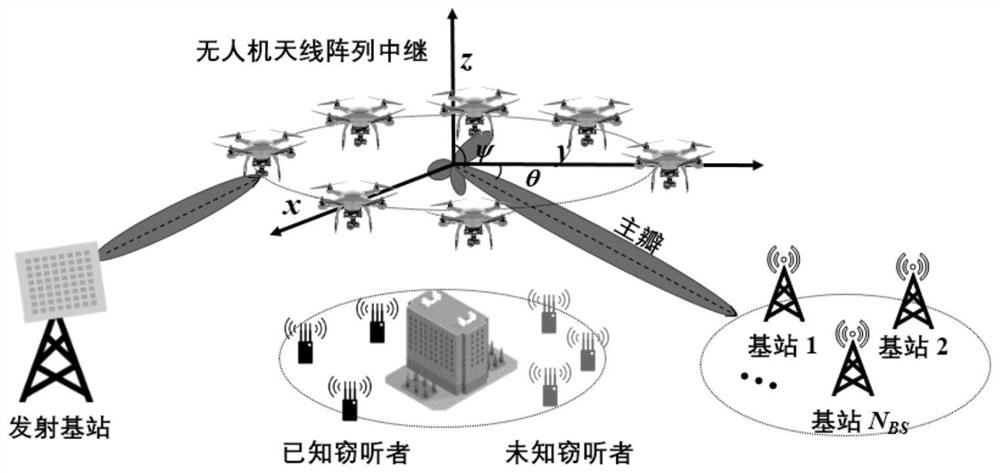
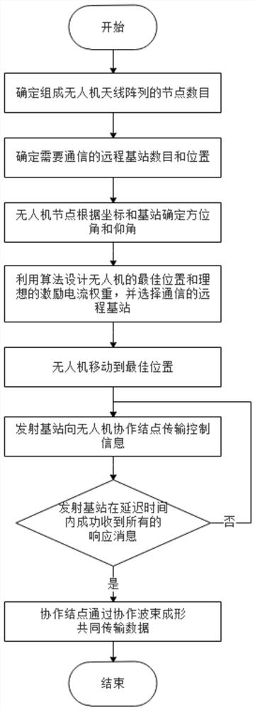
[0038] Such as Figure 1-2 As shown, the present invention provides a UAV relay communication method based on virtual array antenna cooperative beamforming. The transmitting base station (source node) needs to send data to the remote base station through cooperative beamforming of the drone antenna array. These drones that implement cooperative beamforming are called cooperative nodes (drone nodes). The specific process of the communication scheme as follows:

[0039] 1. Determine the number of UAV nodes N that make up the UAV antenna array m .

[0040] First, the minimum value N of the number of UAV nodes is calculated by the following formula m-min ;

[0041]

[0042] Among them, N m >N m-min ;

[0043] In the formula, N m Indicates the number of UAV nodes, P T...


PUM


Abstract

The invention discloses an unmanned aerial vehicle relay communication method based on virtual array antenna cooperative beam forming. The method comprises the following steps: 1, determining the number of unmanned aerial vehicle nodes forming an unmanned aerial vehicle antenna array; 2, determining an azimuth angle and an elevation angle according to positions of the unmanned aerial vehicle nodes and a position of a remote base station needing communication; 3, establishing a calculation model of a transmission rate from the unmanned aerial vehicle antenna array to a receiving base station, a calculation model of the maximum sidelobe level of the unmanned aerial vehicle antenna array and a calculation model of energy consumption of a unmanned aerial vehicle, and determining optimal positions of the unmanned aerial vehicle nodes, an optimal base station communicating with the unmanned aerial vehicle antenna array and an optimal excitation current weight by taking the maximum transmission rate from the unmanned aerial vehicle antenna array to the receiving base station, the minimum maximum sidelobe level of the unmanned aerial vehicle antenna array and the minimum energy consumption of the unmanned aerial vehicle as optimization targets; and 4, after the unmanned aerial vehicle nodes move to the optimal positions, forming a virtual antenna array and transmitting data to the optimal base station by utilizing cooperative beam forming.

Description

technical field [0001] The invention belongs to the technical field of wireless networks, in particular to an unmanned aerial vehicle relay communication method based on cooperative beamforming of virtual array antennas. Background technique [0002] In the field of wireless networks, drones can be used as air base stations and air relays to assist ground networks and provide ground users with reliable and efficient wireless communication services. In the scenario where the UAV is used as an aerial relay, the transmitting base station needs to establish a communication connection with a remote base station cluster. Since the remote base stations can communicate directly, it is only necessary to select a base station from the remote base station cluster to receive information, and it will be responsible for the communication. The base station is regarded as the communication access point. The establishment of links between telecommunication access points can be achieved thro...

Claims


Application Information

Patent Timeline
Patent Type & Authority Applications(China)
IPC IPC(8): H04B7/185H04B7/06
CPCH04B7/18504H04B7/0617Y02D30/70
Inventor 李家辉孙庚郑晓雅刘衍珩梁爽王爱民
Owner JILIN UNIV
Learn More