Evaporator fixing structure
A fixed structure and evaporator technology, applied in the field of evaporators, can solve problems such as displacement and material collision
- Summary
- Abstract
- Description
- Claims
- Application Information
AI Technical Summary
Problems solved by technology
Method used
Image
Examples
Embodiment 1
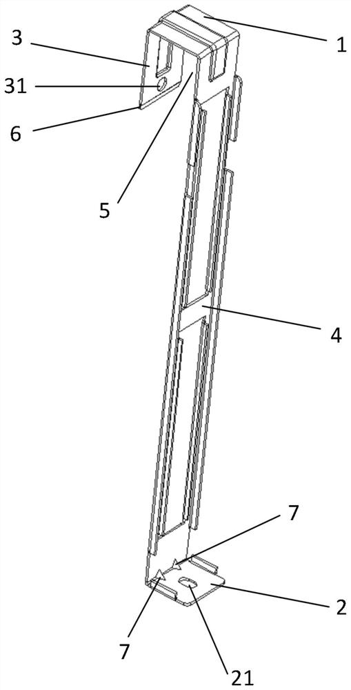
[0036] figure 1 It is a schematic diagram of the fixing structure of the evaporator shown in the embodiment of the present application.
[0037] see figure 1 , the fixed structure of the evaporator includes a first horizontal plate 1, a second horizontal plate 2, a first vertical plate 3 and a second vertical plate 4, the first end of the first vertical plate 3 in the length direction and the second vertical plate 4 are in the The first ends in the length direction are respectively connected to the two ends of the first horizontal plate 1, and the first vertical plate 3 and the second vertical plate 4 are oppositely arranged to form a slot 5, the size of which is the same as that to be fixed. The size of the evaporator is adapted to ensure that the evaporator to be fixed can be clamped into the slot 5; the second horizontal plate 2 is connected to the second end of the second vertical plate 4 in the length direction, and the second horizontal plate 2 Screw holes 21 are provi...
Embodiment 2
[0043] In practical application, on the basis of the first embodiment, in order to facilitate the clamping slot to hold the evaporator, the fixing structure of the evaporator also includes an outer sheet.
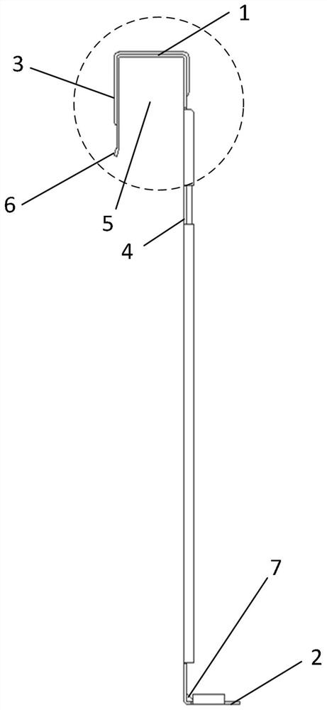
[0044] figure 2 It is another schematic diagram of the evaporator fixing structure shown in the embodiment of the present application;
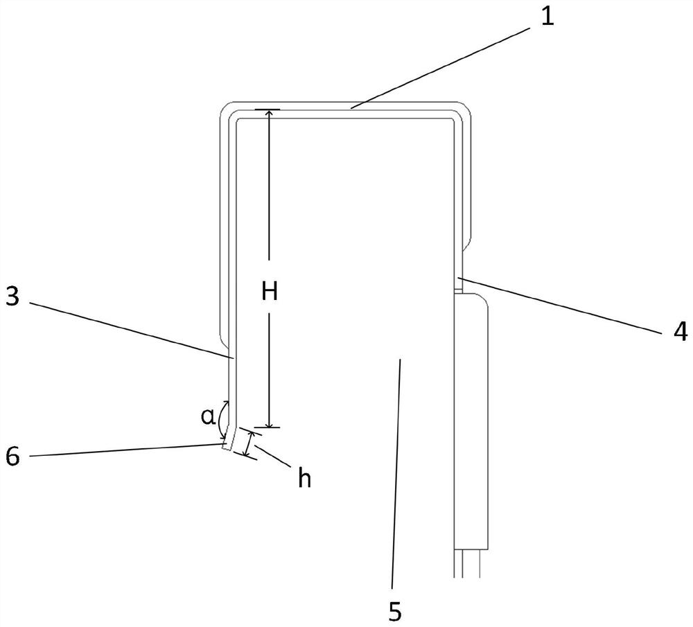
[0045] image 3 yes figure 2 Partial enlarged view of
[0046] Figure 4 It is another schematic diagram of the fixing structure of the evaporator shown in the embodiment of the present application.
[0047] see Figure 1-4 , the outer sheet 6 is connected to the second end of the first vertical board 3 in the length direction, and extends outward, and the turning angle formed with the first vertical board 3 is an obtuse angle α, wherein, the first vertical board 3 and the second vertical board 3 The opposite two sides of riser 4 are inner sides.
[0048] The folding angle α is 150° to 170°, and may be 165°.
[0049] Since the oute...
Embodiment 3
[0055] In practical application, on the basis of the above embodiments, after the card slot is fixed with the evaporator, in order to facilitate fixing with the top plate above the evaporator to be fixed, there are certain requirements on the height of the fixing structure of the evaporator.
[0056] see figure 1 and Figure 4 , the height of the fixing structure of the evaporator is the height L of the second vertical plate 4, the height L of the second vertical plate 4 needs to match the height of the evaporator to be fixed, and the screw holes 21 on the second horizontal plate 2 It is a waist-shaped hole. When screws are used to fix the second horizontal plate 2 to the top plate above the evaporator to be fixed, there may be abnormal fluctuations in the angle and size, and the screw holes 21 are not aligned, which affects the screw fixing. The hole can provide a larger range of motion for screw installation, which is convenient for screw installation.
[0057] It should b...
PUM
 Abstract
Description
Claims
Application Information
 - R&D
- Intellectual Property
- Life Sciences
- Materials
- Tech Scout
- Unparalleled Data Quality
- Higher Quality Content
- 60% Fewer Hallucinations
Browse by: Latest US Patents, China's latest patents, Technical Efficacy Thesaurus, Application Domain, Technology Topic, Popular Technical Reports.
© 2025 PatSnap. All rights reserved.Legal|Privacy policy|Modern Slavery Act Transparency Statement|Sitemap|About US| Contact US: help@patsnap.com


