Device for realizing lower spherical hinge of split mounting type swivel support

An assembled, spherical hinge technology, used in bridge parts, bridges, buildings, etc., can solve the problems of damage and collapse of the swivel bearing and the inability to implement the swivel, so as to reduce the risk of crushing and reduce the stress of the main contact surface. , the effect of increasing safety

Active Publication Date: 2022-01-11
中土集团福州勘察设计研究院有限公司
View PDF9 Cites 0 Cited by
  • Summary
  • Abstract
  • Description
  • Claims
  • Application Information

AI Technical Summary

Problems solved by technology

[0004] The disadvantage of the existing technology is that the lower spherical hinge of the assembled swivel support lower spherical hinge device is divided into multiple pieces for manufacture and installation, and each piece is connected by an anchor bolt, and each piece of the lower spherical hinge is connected with the adjusting bolt by a bolt. Flat steel connection
Due to the concave arc surface of the lower ball joint, the huge vertical force will generate a horizontal component force outward on each lower ball joint. Once the connecting bolts of the lower ball joints connected in blocks are broken under the action of the horizontal force , will lead to the destruction and collapse of the swivel support, and the swivel cannot be implemented, so there is an urgent need for a ball joint device that realizes the assembled swivel support to solve the above problems

Method used


Image

  • Device for realizing lower spherical hinge of split mounting type swivel support
  • Device for realizing lower spherical hinge of split mounting type swivel support
  • Device for realizing lower spherical hinge of split mounting type swivel support

Examples


Embodiment Construction

[0032] In order to enable those skilled in the art to better understand the technical solutions of the present invention, the present invention will be further described in detail below in conjunction with the accompanying drawings.

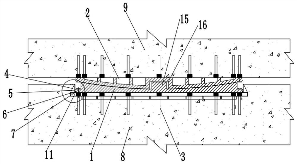
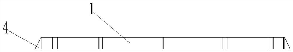
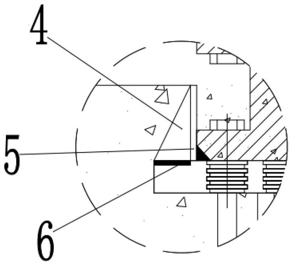
[0033] like Figure 1-10 As shown, a lower spherical hinge device for realizing the assembled swivel support includes a matched lower spherical hinge 1 and an upper spherical hinge 2. The lower spherical hinge 1 includes sub-blocks connected by connectors; it also includes a ring-shaped anti-collapse The structure, the ring-shaped anti-collapse structure includes a ring-shaped reinforcement, which is used to be fixed to the concrete base of the abutment, and the ring-shaped reinforcement is fixedly sleeved on the outer wall of the lower ball hinge 1 .

[0034] The specific embodiment of the present invention provides the lower spherical hinge device for realizing the assembled swivel support, including the matching lower spherical hinge 1 and the...


PUM


Abstract

The invention discloses a device for realizing a lower spherical hinge of a split mounting type swivel support. The device comprises a lower spherical hinge and an upper spherical hinge which are matched with each other, and the lower spherical hinge comprises block bodies which are connected through a connecting piece; and the device further comprises an annular anti-collapse structure, the annular anti-collapse structure comprises an annular reinforcing piece, the annular reinforcing piece is used for being fixed to a concrete base of an abutment, and the annular reinforcing piece is fixedly connected to the outer wall of the lower spherical hinge in a sleeving mode. According to the device for realizing a lower spherical hinge of a split mounting type swivel support, the annular reinforcing piece is arranged, the pressure stress of the contact face of the lower spherical hinge of the swivel support and bearing platform concrete is reduced through the annular reinforcing piece, and the annular reinforcing piece can also provide constraining force on the lower spherical hinge of the swivel support; and in addition, after partial block bodies of the lower spherical hinge are pressed and collapsed, the lower spherical hinge can still keep running without deformation, so that the safety of the swivel support is greatly improved, and the risk that the contact surface of the lower spherical hinge of the swivel support and concrete is crushed due to overlarge pressure stress is also reduced.

Description

technical field [0001] The invention relates to bridge construction technology, in particular to a spherical hinge device for realizing an assembled swivel support. Background technique [0002] With the development of my country's transportation industry, many new projects have problems such as highways and railway bridges need to cross roads, rivers, deep ditches and other various terrains. In order to solve such problems, the plane swivel construction method is one of the most widely used construction methods at present. The device used in this construction method is called a bridge swivel device; It is composed of vinyl fluoride slide plate, leveling steel plate, pin shaft and anchor bolt connecting the upper and lower ball joints. At present, swivel bearings are divided into integral type and block assembly type. Integral swivel bearings are generally suitable for conventional size swivel bearings with a swivel mass of less than 30,000 tons. For swivel bearings with a...

Claims


Application Information

Patent Timeline
Patent Type & Authority Applications(China)
IPC IPC(8): E01D19/04
CPCE01D19/046E01D19/041
Inventor 张建森高冬平陈进蔡华炳张建新
Owner 中土集团福州勘察设计研究院有限公司
Why Eureka
Try Eureka