Underground assembly type building waterproof structure
A building waterproof and assembly technology, applied in the engineering field, can solve problems such as poor waterproof effect, achieve the effect of reducing collapse, avoiding accumulation and improving durability
- Summary
- Abstract
- Description
- Claims
- Application Information
AI Technical Summary
Problems solved by technology
Method used
Image

Examples
Embodiment 1
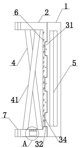
[0036] refer to Figure 1-4 , an underground prefabricated building waterproof structure described in this embodiment includes a first splicing plate 1 and a second splicing plate 2, a moisture-proof component 3 is arranged between the first splicing plate 1 and the second splicing plate 2, and the second splicing plate The inner side of the splicing plate 2 is provided with a support assembly 4, the inner side of the second splicing plate 2 is provided with a groove 8, the inside of the groove 8 is fixedly installed with a drainage pipe 9, and the inner left side of the second splicing plate 2 is provided with an array Water guide groove 6, when installing, the second splicing plate 2 is the inner side close to the base layer, the first splicing plate 1 is the outside, and the waterproof felt 33 is provided with a through hole matched with the sealing hole 34, by setting the first splicing plate 1 and the second splicing plate The receiving block 31 and the receiving groove 3...
Embodiment 2
[0038] refer to Figure 4 , on the basis of embodiment 1, in order to achieve the purpose of drainage, the upper side of the lower end of the second splicing plate 2 of the present embodiment is provided with a water guide hole 10, and the water guide hole 10 is connected with the drain pipe 9; The hole 10 is convenient to discharge the water seeping into the inner side of the second splicing plate 2 into the drain pipe 9, so as to avoid accumulation and affect the second splicing plate 2.
[0039] refer to figure 1 , in order to achieve the purpose of installation, the upper and lower ends of the second splicing plate 2 in this embodiment are provided with an array of mounting holes 7; by setting the array of mounting holes 7 on the second splicing plate 2, the second splicing plate 2 can be installed and fixed. role.
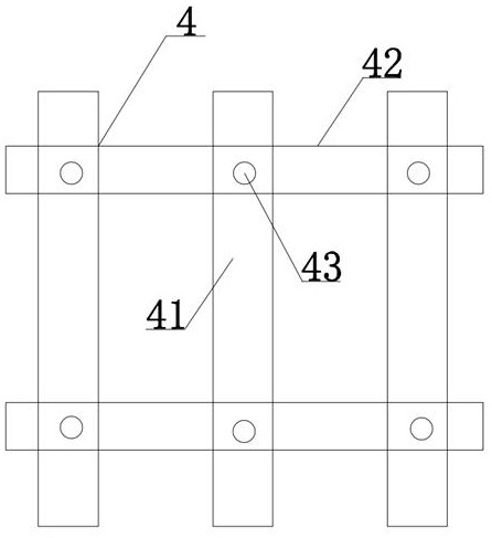
[0040] refer to figure 1 with image 3 , in order to achieve the purpose of fixedly supporting the second splicing plate 2, the supporting assembly 4 of t...
Embodiment 3
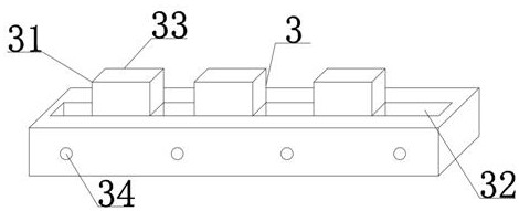
[0042] refer to Figure 1-2, this embodiment is on the basis of embodiment 1, in order to achieve the purpose of moisture-proof, this embodiment carried out innovative design to the moisture-proof component 3, specifically, the moisture-proof component 3 comprises receiving block 31 and receiving groove 32, and receiving block 31 is respectively fixed Connected to one side of the first splicing plate 1 and the second splicing plate 2, the receiving grooves 32 are respectively opened on one side of the first splicing plate 1 and the second splicing plate 2, the receiving block 31 matches the receiving groove 32, and the receiving block 31 and receiving groove 32 are arranged alternately, and the interior of receiving groove 32 is fixedly connected with waterproof felt 33, the thickness of waterproof felt 33 is 3-5mm, and both sides of the first splicing plate 1 and the second splicing plate 2 are provided with sealing holes 34, the sealing hole 34 is connected with the receivin...
PUM
 Abstract
Description
Claims
Application Information
 - R&D
- Intellectual Property
- Life Sciences
- Materials
- Tech Scout
- Unparalleled Data Quality
- Higher Quality Content
- 60% Fewer Hallucinations
Browse by: Latest US Patents, China's latest patents, Technical Efficacy Thesaurus, Application Domain, Technology Topic, Popular Technical Reports.
© 2025 PatSnap. All rights reserved.Legal|Privacy policy|Modern Slavery Act Transparency Statement|Sitemap|About US| Contact US: help@patsnap.com