Health monitoring mattress and no-load heart impact and respiration monitoring system

A technology for health monitoring and mattresses, applied in mattresses, spring mattresses, measuring pulse rate/heart rate, etc., can solve problems such as inability to receive timely care in emergencies, inability to call for help or delay in calling for help, and patient discomfort. To achieve the effect of changeable power supply mode, good practicability and real and reliable data

Pending Publication Date: 2022-01-14
TIANJIN ZEM INTELLINGENT TECH CO LTD
View PDF0 Cites 1 Cited by
  • Summary
  • Abstract
  • Description
  • Claims
  • Application Information

AI Technical Summary

Problems solved by technology

In addition, for patients and the elderly, it is very easy for patients and the elderly to fail to call for help or call for help in a sudden illness while lying in bed or sleeping, resulting in getting up and falling at night, and failing to receive timely care for emergencies. will be more serious
[0003] Existing monitoring of clinical morbidity mostly uses external means such as ECG monitors to monitor vital signs such as heart rate, respiratory rate, blood pressure, blood oxygen, pulse, body temperature, etc. The possibility of parameters being missed, but it is necessary to use contact measurement or real-time monitoring. The patient is connected to the ECG electrode and other cables, which will cause discomfort to the patient for a long time, especially in the process of general measurement or real-time monitoring. Requirements for lying down and lying down are not conducive to long-term measurement or monitoring
For the monitoring of physical signs in the process of elderly care and rehabilitation, it is even more unsuitable to wear external equipment such as electrodes for long-term monitoring.

Method used


Image

  • Health monitoring mattress and no-load heart impact and respiration monitoring system
  • Health monitoring mattress and no-load heart impact and respiration monitoring system
  • Health monitoring mattress and no-load heart impact and respiration monitoring system

Examples


Embodiment 1

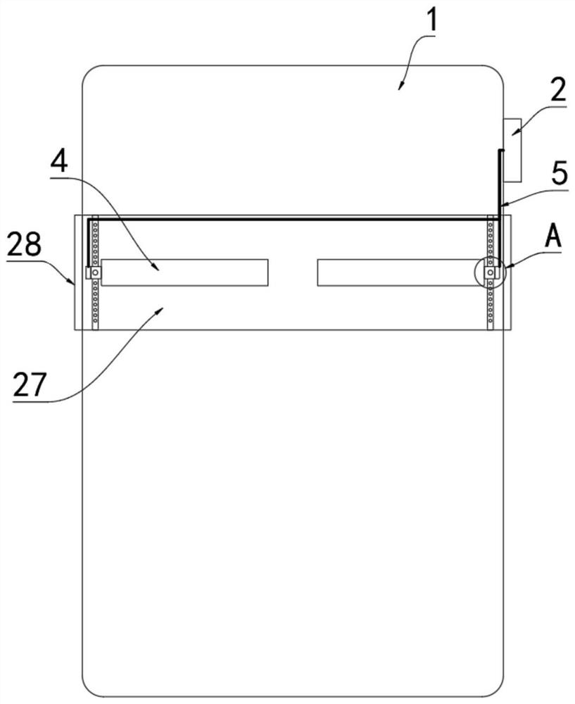
[0033] refer to Figure 1-2 , including a mattress body 1, a piezoelectric sensor module, and a signal acquisition board 2, the signal acquisition board 2 is arranged outside the mattress body 1, and an inner cavity 27 is provided in the mattress body 1, and the inner cavity 27 runs through the mattress body 1 left and right, And the two ends of the inner cavity 27 are sealed by a zipper 28 .

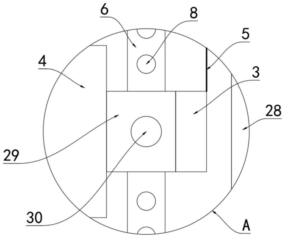
[0034] The sensor module includes a signal wiring port 3 and a sensor strip 4 laid on the mattress body 1, the sensor strip 4 is located in the inner cavity 27, the sensor strip 4 and the signal wiring port 3 are two groups, and the sensor strip 4 and The signal connection port 3 is set in one-to-one correspondence, the signal connection port 3 is connected with the sensor belt 4, and two sub-signal lines 5 are installed on the signal acquisition board 2, and the two sub-signal lines 5 are respectively connected with the two signal connection ports 3; Wherein, a power line 7 is connect...

Embodiment 2

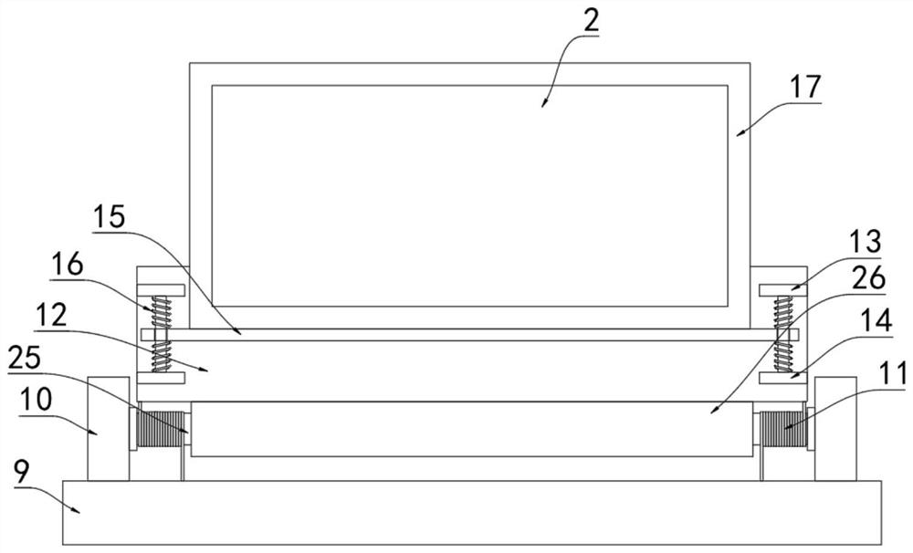
[0038] refer to image 3The difference between this embodiment and Embodiment 1 is that a support plate 9 is installed on the bottom of the mattress body 1 in this embodiment, and two vertical blocks 10 are fixedly connected to the support plate 9, and the two vertical blocks 10 are connected by rotation. There is a resettable mounting rod 25, two torsion springs 11 are installed between the mounting rod 25 and the support plate 9, and a mounting plate 26 is installed on the mounting rod 25.

[0039] The upper end of the mounting plate 26 is fixedly connected with a riser 12, and a housing 17 is installed on the riser 12. An upper and lower buffer mechanism is arranged between the housing 17 and the riser 12. Fixed block 13 and two lower fixed blocks 14, two lower fixed blocks 14 are positioned at the below of two upper fixed blocks 13 respectively, between the upper fixed block 13 that is arranged oppositely and the lower fixed block 14 is fixedly connected with guide bar, tw...

Embodiment 3

[0043] refer to Figure 4-5 The difference between this embodiment and Embodiments 1 and 2 is that the buffer mechanism in this embodiment includes two upper fixing blocks 13 and two lower fixing blocks 14 fixed on the riser 12, and the two lower fixing blocks 14 are respectively located Below the two upper fixed blocks 13, a guide rod is fixedly connected between the upper fixed block 13 and the lower fixed block 14 which are arranged oppositely, and the outside of the two guide rods is sheathed with a moving plate 15; down, making the moving plate 15 move more stably.

[0044] The housing 17 is in contact with the upper end of the moving plate 15, and the bottom of the housing 17 is fixedly connected with two connecting blocks 19, and the moving plate 15 is provided with two connecting holes 18 up and down, and the two connecting blocks 19 respectively pass through the two connecting holes 18 set, and the bottom of the moving plate 15 is equipped with two limit mechanisms, ...


PUM


Abstract

The invention discloses a health monitoring mattress which comprises a mattress body, a piezoelectric sensor module and a signal acquisition board, and is characterized in that the signal acquisition board is arranged outside the mattress body, an inner cavity is formed in the mattress body, the sensor module comprises signal wiring ports and sensing belts laid on the mattress body, the sensing belts are located in the inner cavity, the sensing belts and the signal wiring ports are divided into two groups, the sensing belts and the signal wiring ports are arranged in a one-to-one correspondence mode, and the signal wiring ports are connected with the sensing belts. By arranging the resistance type pressure sensor, monitoring of human body pressure signals is achieved, the power supply mode is variable, the human body pressure signals can be accurately collected, the heart rate and respiration rate can be calculated, and it is known through actual measurement that the heartbeat per minute displayed by the heart rate monitoring system and the PPG sensing module only has the difference within plus or minus 5, the accuracy rate can reach 96.3%, and the result shows that the data of the system is real and reliable.

Description

technical field [0001] The invention relates to the technical field of human health monitoring, in particular to a health monitoring mattress and a no-load cardiac shock and breathing monitoring system. Background technique [0002] With the improvement of people's living standards, people pay more and more attention to health. A smart mattress that can monitor human vital signs (such as heart rate and breathing rate) and common diseases (such as atrial fibrillation and apnea) in real time is becoming more and more popular. more popular with users. In addition, for patients and the elderly, it is very easy for patients and the elderly to fail to call for help or call for help in a sudden illness while lying in bed or sleeping, resulting in getting up and falling at night, and failing to receive timely care for emergencies. will be more serious. [0003] Existing monitoring of clinical morbidity mostly uses external means such as ECG monitors to monitor vital signs such as ...

Claims


Application Information

Patent Timeline
Patent Type & Authority Applications(China)
IPC IPC(8): A61B5/11A61B5/0205A61B5/00A47C23/00A47C27/00
CPCA61B5/1102A61B5/0205A61B5/4809A61B5/4812A61B5/4815A61B5/024A61B5/0816A61B5/1118A61B5/6892A61B5/6891A61B5/7225A47C23/00A47C27/00A61B2562/0247
Inventor 娄辉王皓
Owner TIANJIN ZEM INTELLINGENT TECH CO LTD
Why Eureka
Try Eureka