
Simple pipe cutting machine

A pipe cutting machine and simple technology, applied in pipe cutting devices, shearing devices, metal processing machinery parts, etc., can solve the problems of high labor intensity of operators, troublesome manual feeding, low pipe accuracy, etc., and improve cutting efficiency. , cutting convenience and precision, easy to use effect

Pending Publication Date: 2022-01-14
GUANGZHOU HANMA AUTOMATION CONTROL EQUIP CO LTD
View PDF7 Cites 0 Cited by
  • Summary
  • Abstract
  • Description
  • Claims
  • Application Information

AI Technical Summary

Problems solved by technology

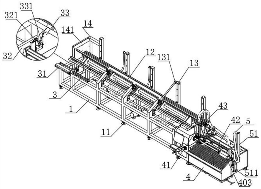
[0004] The purpose of the present invention is to provide a simple pipe cutting machine, which aims to improve the traditional manual feeding method used in the cutting process of the existing pipe cutting machine. Because the pipe itself has a large net weight and a long length, it is difficult to manually Loading is very troublesome, the efficiency is low, the cut pipes need to be manually deburred and aggregated, the efficiency is low, the precision of the pipes obtained after processing is not high, and the labor intensity of the operator is high.

Method used


Image

  • Simple pipe cutting machine
  • Simple pipe cutting machine
  • Simple pipe cutting machine

Examples


Embodiment Construction

[0024] Embodiments of the present invention are described in detail below, and examples of the embodiments are shown in the drawings, wherein the same or similar reference numerals denote the same or similar elements or elements having the same or similar functions throughout. The embodiments described below by referring to the figures are exemplary only for explaining the present invention and should not be construed as limiting the present invention.

[0025] In the description of the present invention, it should be understood that the orientation descriptions, such as up, down, front, back, left, right, etc. indicated orientations or positional relationships are based on the orientations or positional relationships shown in the drawings, and are only In order to facilitate the description of the present invention and simplify the description, it does not indicate or imply that the device or element referred to must have a specific orientation, be constructed and operated in ...


PUM


Abstract

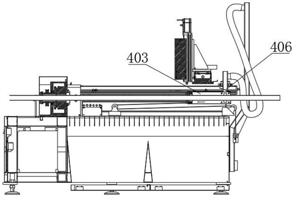
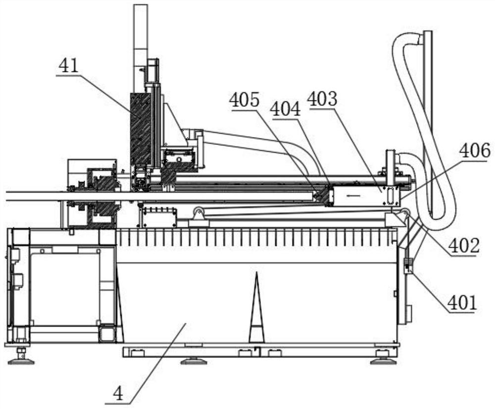
The invention discloses a simple pipe cutting machine. The simple pipe cutting machine comprises a feeding supporting frame, a feeding mechanism is arranged on one side of the interior of the feeding supporting frame, a conveying mechanism is arranged in one end of the feeding supporting frame, a cutting mechanism is arranged at one end of the feeding supporting frame, and a limiting mechanism and a dust collection mechanism are arranged on the cutting mechanism. The simple pipe cutting machine has the characteristics of being reasonable in structure and convenient to use, through mutual cooperation between the arranged feeding mechanism and the arranged conveying mechanism, automatic feeding of to-be-cut pipes can be achieved, and then the pipe cutting efficiency can be improved; through mutual cooperation between the arranged cutting mechanism and the arranged limiting mechanism, pipe cutting is more convenient and accurate; and through the arrangement of the dust collection mechanism, chippings generated during pipe cutting can be effectively cleaned away.

Description

technical field [0001] The invention relates to the technical field of cutting machines, in particular to a simple pipe cutting machine. Background technique [0002] With the rapid development of the domestic economy, the application of pipes is becoming more and more common, especially in construction, machinery and other industrial fields. In conventional production, it is necessary to cut long pipes into small pieces of pipes, and different application fields have special requirements for the length accuracy and shape accuracy of pipes, so it is necessary to use special pipe cutting equipment to cut pipes, and cutting As a common pipe cutting equipment, pipe machine is widely used in industrial production. [0003] However, the existing pipe cutting machine adopts the traditional manual feeding method in the cutting process. Due to the large net weight and quality of the pipe itself and the long length, manual feeding is very troublesome and inefficient, and the cut pip...

Claims


Application Information

Patent Timeline
Patent Type & Authority Applications(China)
IPC IPC(8): B23Q7/00B23Q7/06B23Q11/00B23D21/00B23D33/02
CPCB23Q7/00B23Q7/06B23Q11/0046B23D21/00B23D33/02
Inventor 陈绵著
Owner GUANGZHOU HANMA AUTOMATION CONTROL EQUIP CO LTD
Learn More