
Starlight-level high-definition network spherical intelligent camera

A smart camera, starlight-level technology, applied in the field of cameras, can solve the problems of increased installation limitations and inconveniences, inconsistent camera heights, and difficult temperature drainage, etc., to increase stability and temperature control efficiency, increase adjustability and Flexibility, improved torque and stability

Pending Publication Date: 2022-01-14
SHENZHEN BOLIN IMAGE SCI TECH
View PDF0 Cites 0 Cited by
  • Summary
  • Abstract
  • Description
  • Claims
  • Application Information

AI Technical Summary

Problems solved by technology

[0003] The current starlight cameras often have built-in heaters and blowers to reduce condensation under severe temperature changes. However, the cameras often require housing protection, so it is difficult to vent the temperature inside the device, which increases the difficulty in the operation of the camera's heating and cooling system. At the same time, it is difficult to intelligently control the inside of the camera to make adjustments and changes according to the ac

Method used


Image

  • Starlight-level high-definition network spherical intelligent camera
  • Starlight-level high-definition network spherical intelligent camera
  • Starlight-level high-definition network spherical intelligent camera

Examples


Example Embodiment

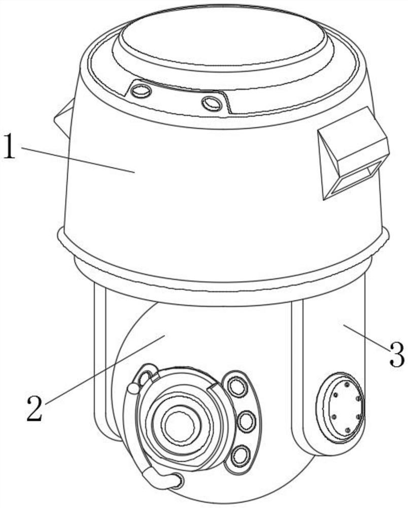
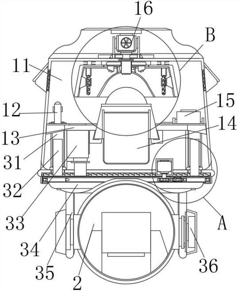
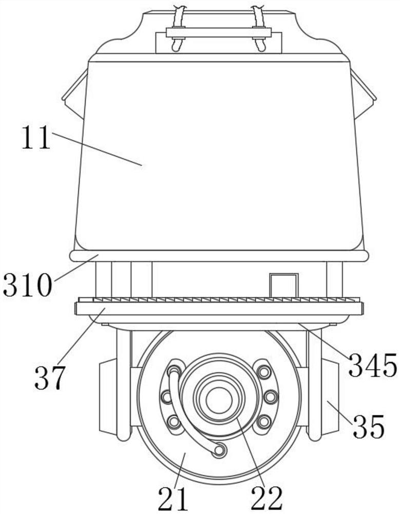
[0038] Example 1, as Figure 1-3 As shown, when the intelligent temperature control system 16 performs heat dissipation work, the annular groove 37 and the annular groove 310 can be separated by the activation of the miniature electric push rod 33, so as to promote the circulation under the installation shell 11, and the miniature blower can be used at this time. The radiating airflow blown by the 161 quickly discharges the heat to the outside, which greatly improves the work efficiency of the cooling of the camera components, and increases the coordination and controllability of the device structure.

Example Embodiment

[0039] Example 2, as Figure 5 As shown, when the annular groove 37 and the annular groove 310 are engaged and spliced ​​with each other, the first helical gear ring 38 and the second helical gear ring 39 can be engaged and fixed to effectively improve the sealing performance of the annular groove 37 and the annular groove 310 At the same time, the first helical gear ring 38 and the second helical gear ring 39 are used to hide and seal inside the annular groove 310 to further improve the fit and sealing effect of the annular groove 37 and the annular groove 310, so as to prevent the penetration of cold flow from the outside. Inside the device, increase the protection of the device.

[0040] Working principle: When the device is in use, first place the camera in the designated position. When the height is inconsistent, the annular groove 37 can be driven down by the telescopic guide of the two sets of inner sleeves 32 and outer sleeves 31 through the activation of the miniature...


PUM


Abstract

The invention discloses a starlight-level high-definition network spherical intelligent camera. The camera comprises a shell component, a starlight-level camera system and an intelligent adjusting mechanism, wherein the shell component comprises a mounting shell, a temperature sensor, a transverse plate, a high-definition network module, a remote control module and an intelligent temperature control system; and the transverse plate is fixedly connected to middle positions of two sides of the interior of the mounting shell. According to the invention, through the intelligent temperature control system arranged in the mounting shell, the interior of the mounting shell is promoted to obtain an intelligent temperature control effect under the cooperative control of the temperature sensor and the remote control module, that is, the camera can be adaptively adjusted in a high or low temperature environment; and mutual coordination of a guiding frame and a guide structure of a guiding gutter is utilized, so that cooling air and heating air flow in the mounting shell more uniformly, overheated parts are cooled quickly, the condensation phenomenon is prevented, and the operation stability and the temperature control efficiency of the camera are improved.

Description

technical field [0001] The invention relates to the field of camera technology, in particular to a star-level high-definition network dome smart camera. Background technique [0002] Starlight dome camera is a powerful high-speed dome camera with a solid shell and IP67 protection, which is suitable for extreme weather environments. Get excellent color images under all conditions. [0003] The current starlight cameras often have built-in heaters and blowers to reduce condensation under severe temperature changes. However, the cameras often require housing protection, so it is difficult to vent the temperature inside the device, which increases the difficulty in the operation of the camera's heating and cooling system. At the same time, it is difficult to intelligently control the inside of the camera to make adjustments and changes according to the actual ambient temperature, which will easily cause the structural components in the camera to suffer from condensation and ove...

Claims


Application Information

Patent Timeline
IPC IPC(8): H04N5/225H04N5/232F16M11/12F16M11/18G03B17/55
CPCG03B17/55F16M11/12F16M11/18H04N23/51H04N23/50H04N23/661H04N23/695
Inventor 郭光泉
Owner SHENZHEN BOLIN IMAGE SCI TECH
Learn More