Transformer convenient to install

A technology of transformers and regulating devices, applied in the field of transformers, can solve the problems of inconvenient staff, unsteady installation of the main body of the transformer, and many manpower, and achieve the effects of reducing labor intensity, avoiding unstabilized installation, and improving installation efficiency

Inactive Publication Date: 2022-01-18
陈金枝
View PDF0 Cites 2 Cited by
  • Summary
  • Abstract
  • Description
  • Claims
  • Application Information

AI Technical Summary

Problems solved by technology

[0004] The purpose of the present invention is to provide a transformer that is easy to install, to solve the problem that the existing transformer proposed in the above background technology needs to install the transformer body at a higher position when it is in use, so there will be problems during the installation process. Personnel will cause a certain degree of inconvenience, and during installation, if there is a deviation between the reserved hole and the connection hole, it will cause the main body of the transformer to be unable to be installed stably, and it will consume more manpower and material resources, causing a certain degree of economic loss to the user. loss problem

Method used


Image

  • Transformer convenient to install
  • Transformer convenient to install
  • Transformer convenient to install

Examples


Embodiment 1

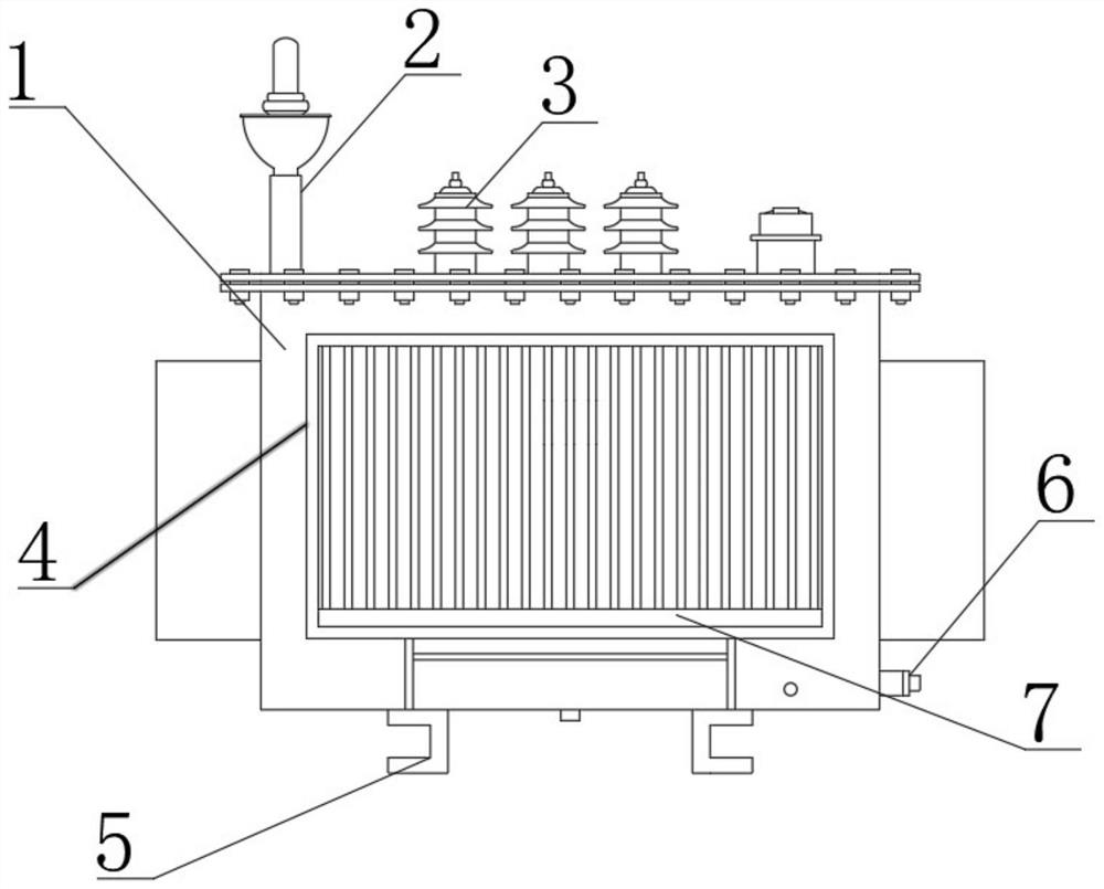
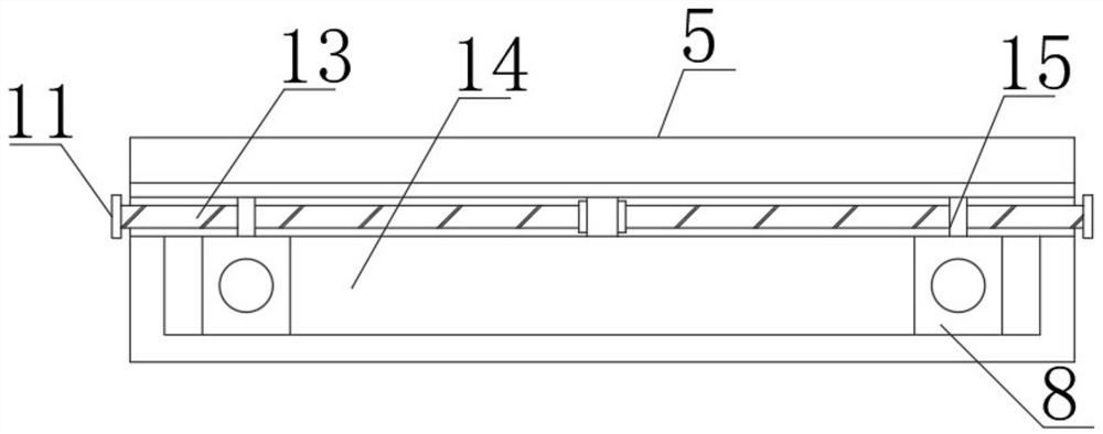
[0022] see Figure 1-Figure 3 , the present invention provides a technical solution: a transformer that is easy to install, including a transformer main body 1, a high-voltage bushing 2 is fixed on the top of the transformer main body 1 by bolts, and one side of the high-voltage bushing 2 is fixed to the top of the transformer main body 1 by bolts. The low-voltage bushing 3, the side of the transformer main body 1 is welded with an oil outlet 6, the bottom of the transformer main body 1 is fixed with a fixed plate 5 by bolts, and the top surface of the fixed plate 5 is provided with a bolt hole 10, and the transformer main body 1 also includes an adjustment device, which is set At the bottom of the transformer main body 1, the adjustment device includes a movable slot 14, the inner side of the movable slot 14 is connected with a movable block 8 through snap-fitting, the surface of the movable block 8 is provided with a connecting hole 12, and one side of the movable slot 14 is ...

Embodiment 2

[0026] see Figure 1-Figure 4 , the present invention provides a technical solution: a transformer that is easy to install, including a transformer main body 1, a high-voltage bushing 2 is fixed on the top of the transformer main body 1 by bolts, and one side of the high-voltage bushing 2 is fixed to the top of the transformer main body 1 by bolts. The low-voltage bushing 3, the side of the transformer main body 1 is welded with an oil outlet 6, the bottom of the transformer main body 1 is fixed with a fixing plate 5 by bolts, the top surface of the fixing plate 5 is provided with a bolt hole 10, and the transformer main body 1 also includes an adjustment device and a cleaning device, The adjusting device is arranged at the bottom of the transformer main body 1, and the adjusting device includes a movable slot 14. The inner side of the movable slot 14 is connected with the movable block 8 through snap-fitting, and the surface of the movable block 8 is provided with a connection...


PUM


Abstract

The invention discloses a transformer convenient to install, and the transformer comprises a transformer body; a high-voltage sleeve is fixed to the top of the transformer body through a bolt, a low-voltage sleeve is fixed to one side, opposite to the top of the transformer body, of the high-voltage sleeve through a bolt, and an oil outlet is welded to the side face of the transformer body; a fixed plate is fixed to the bottom of the transformer body through bolts, bolt holes are formed in the surface of the top of the fixing plate, and the transformer body further comprises an adjusting device and a cleaning device. Through the adjusting device designed at the bottom of the transformer main body, a worker can conveniently adjust the position of the connecting hole in the installation process, the installation efficiency of the worker is effectively improved, through the cleaning device designed on the surface of the transformer main body, the worker can conveniently clean the surface of the heat dissipation plate regularly, and the situation that the heat dissipation plate cannot effectively dissipate heat due to the fact that much dust is attached to the surface of the heat dissipation plate is avoided.

Description

technical field [0001] The invention belongs to the technical field of transformers, and in particular relates to a transformer that is easy to install. Background technique [0002] The transformer is a device that uses the principle of electromagnetic induction to change the AC voltage. The main components are the primary coil, the secondary coil and the iron core (magnetic core). The main functions are: voltage conversion, current conversion, impedance conversion, isolation, voltage stabilization (magnetic Saturated transformer), etc., the principle of transformer voltage transformation was first discovered by Faraday, but it was not practically applied until the 1880s. [0003] However, there are still some deficiencies in the existing transformers during use: when the existing transformers are in use, because the main body of the transformer needs to be installed at a higher position, it will cause a certain degree of damage to the staff during the installation process....

Claims


Application Information

Patent Timeline
Patent Type & Authority Applications(China)
IPC IPC(8): H01F27/02H01F27/06H01F27/08B08B1/00
CPCH01F27/02H01F27/06H01F27/025H01F27/08B08B1/002B08B1/008
Inventor 陈金枝
Owner 陈金枝
Why Eureka
Try Eureka