Coiled material cutting device with fixed distance for leather product production

A coil cutting and spacing technology, applied in leather punching/punching/cutting, application, raw hide/leather/fur manufacturing equipment, etc., can solve the problems of coil cutting position offset, insufficient uniform force, etc.

Inactive Publication Date: 2022-01-21
湖南泰瑞莎皮具有限公司
View PDF0 Cites 0 Cited by
  • Summary
  • Abstract
  • Description
  • Claims
  • Application Information

AI Technical Summary

Problems solved by technology

[0003] The technical problem to be solved by this technical solution is: the present invention provides auxiliary positioning structures for both sides of the blade in the cutting structure to position the coiled material, and solves the problem of the coiled material caused by the uneven force of the blade during the cutting process of the coiled material. The problem of material cutting position offset

Method used


Image

  • Coiled material cutting device with fixed distance for leather product production
  • Coiled material cutting device with fixed distance for leather product production
  • Coiled material cutting device with fixed distance for leather product production

Examples


Embodiment 1

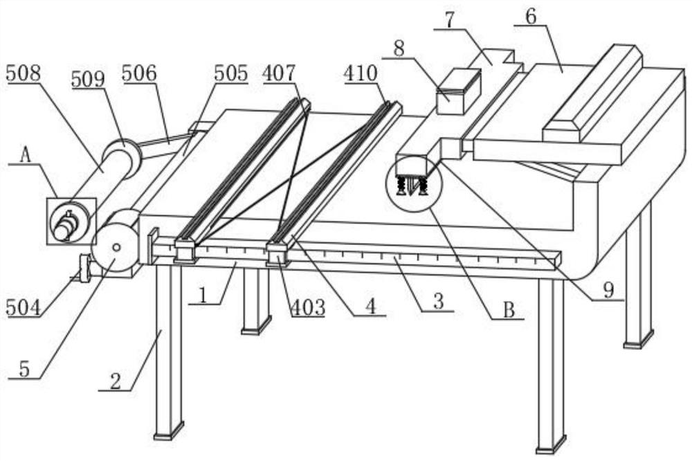
[0037]A fixed-distance coil material cutting device for leather goods production, comprising a workbench 1, a foot 2 is connected to the bottom end of the workbench 1, a measuring ruler 3 is connected to the front end of the workbench 1, and the measuring ruler 3 The top of the workbench 1 is provided with a fixed distance structure 4, and the top side of the workbench 1 is provided with a servo telescopic frame 6, and one side of the servo telescopic frame 6 is connected with a complete machine 7, and the top of the complete machine 7 is connected with a motor 8. The output end of the motor 8 is provided with a cutting structure 9, the cutting structure 9 includes an integrated plate 901, the middle of the bottom end of the integrated plate 901 is connected with a blade 902, and the bottom end of the integrated plate 901 is a Both sides are provided with a buffer column 903, the buffer column 903 runs through the integration plate 901, and the buffer column 903 is slidingly co...

Embodiment 2

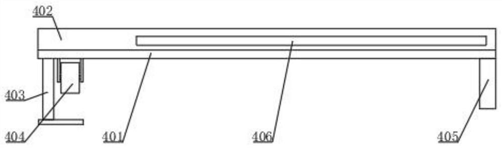
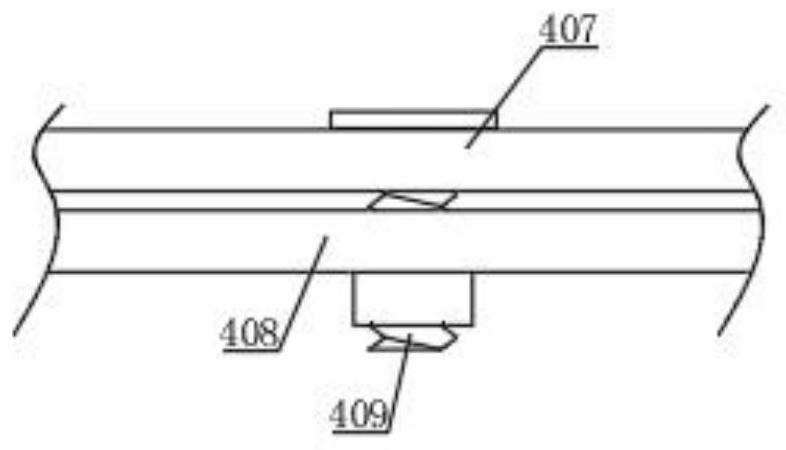
[0039] As a further optimization scheme of the above embodiment: the fixed distance structure 4 includes a bottom plate 401, and the bottom plate 401 is slidingly connected with the workbench 1, the top of the bottom plate 401 is connected with a spacer 402, and the bottom plate 401 on one side The outer side of the first connecting shaft 407 is rotatably connected, and the first connecting shaft 407 is slidably connected with the bottom plate 401 on the other side, and the second connecting shaft 408 is rotated on the outer side of the bottom plate 401 on the other side, and the second The connecting shaft 408 is slidingly connected to the bottom plate 401 on one side, and the middle position of the first connecting shaft 407 is provided with a positioning threaded shaft 409, and the positioning threaded shaft 409 runs through the first connecting shaft 407 and the second connecting shaft 408, and The positioning threaded shaft 409 is rotationally connected with the first conn...

Embodiment 3

[0041] As a further optimization scheme of the above-mentioned embodiment: the bottom end side of the bottom plate 401 is connected with a first splint 403, and the first splint 403 is slidably connected with the measuring ruler 3, and the top of the measuring ruler 3 is slidably connected with a pulley 404, And the pulley 404 is connected with the bottom plate 401, and the other side of the bottom end of the limit frame 402 is connected with a second splint 405, and the second splint 405 is slidably connected with the workbench 1, directly pushing the bottom plate 401 to be positioned by the first splint 403 One side of the ruler 3 is measured, and the second splint 405 is positioned on the outside of the workbench 1 to keep the bottom plate 401 moving smoothly on the workbench 1 .


PUM


Abstract

The invention relates to the technical field of leatherware coiled material cutting, in particular to a coiled material cutting device with fixed distance for leather product production. The coiled material cutting device comprises a working table, supporting legs are connected to the bottom end of the working table, a measuring scale is connected to the front end of the working table, a fixed-distance structure is arranged at the top end of the measuring scale, a servo telescopic frame is arranged on one side of the top end of the working table, and an overall unit is connected to one side of the servo telescopic frame. According to the coiled material cutting device with the fixed distance for leather product production, through the arrangement of an integration plate, a blade, a buffering column and a spring, connection between the integration plate and the blade, sliding connection between the buffering column and the integration plate and sliding connection between the spring and the buffering column are matched, and a motor drives the integration plate at the bottom end of the whole to move downwards; and the blade and the buffering column are controlled to descend synchronously, the buffering column firstly makes contact with a coiled material on the lower portion to position the coiled material, along with continuous descending of the integration plate, the buffering column extrudes the spring on the outer side to be subjected to compression deformation, so that the blade does not conduct winding displacement when cutting the coiled material, and cutting is completed.

Description

technical field [0001] The invention relates to the field of leather coil cutting, in particular to a coil cutting device with a fixed distance for leather production. Background technique [0002] Leather goods are leather furniture or leather tools made of leather, such as leather sofas, leather chairs, leather beds, leather bags, leather whips, leather gloves and other leather products. In a broad sense, leather goods also include leather clothes, leather shoes and other leather products. The coil cutting device used in the production of leather goods on the market needs to use a tape measure to measure the size of the coil. This measurement method also needs to use a marker pen to mark and cut the coil, which is less practical. At the same time, when the coil needs to be moved, Generally, the staff directly carry the coiled material, which is very inconvenient to operate. When cutting the coiled material, because the cutting force is not stable enough, it is easy to caus...

Claims


Application Information

Patent Timeline
IPC IPC(8): C14B5/00C14B17/08
CPCC14B5/00C14B17/08
Inventor 王琳李细兰魏巍舒煜喜唐海云
Owner 湖南泰瑞莎皮具有限公司
Why Eureka
Try Eureka