
Fabricated bridge beam end telescopic deformation coordination structure and mounting method thereof

A deformation coordination and assembly technology, applied in the erection/assembly of bridges, bridges, bridge parts, etc., can solve the problems of affecting normal traffic, time-consuming, and maintenance time-consuming, etc., to shorten the construction period, facilitate installation, and ease The effect of replacing the installation

Pending Publication Date: 2022-01-21
JSTI GRP CO LTD +1
View PDF7 Cites 2 Cited by
  • Summary
  • Abstract
  • Description
  • Claims
  • Application Information

AI Technical Summary

Problems solved by technology

[0002] At present, prefabricated bridges generally need to install expansion joints at the ends of the beams. The conventional practice is to chisel the ends of the beams at the joints after the prefabricated bridges are installed on site, so as to install expansion devices and pour concrete. The above-mentioned conventional method generally takes about 15 days to complete the construction period, which takes a long time
At the same time, once the traditional telescopic device is damaged, the beam end needs to be destructively removed and replaced, and the maintenance period will take a long time, which will affect the normal traffic

Method used


Image

  • Fabricated bridge beam end telescopic deformation coordination structure and mounting method thereof
  • Fabricated bridge beam end telescopic deformation coordination structure and mounting method thereof
  • Fabricated bridge beam end telescopic deformation coordination structure and mounting method thereof

Examples


Embodiment Construction

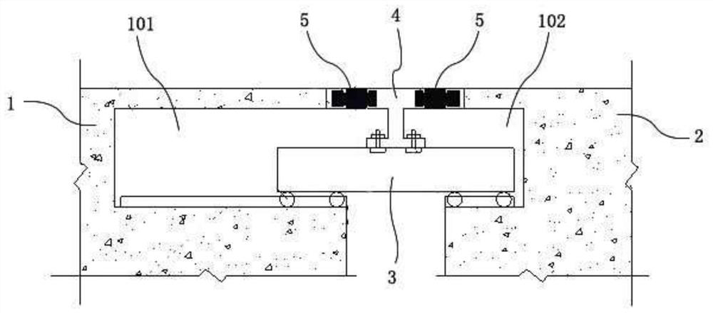
[0041] The present invention will be further described below in conjunction with the accompanying drawings. The following examples are only used to illustrate the technical solution of the present invention more clearly, but not to limit the protection scope of the present invention.

[0042] In describing the present invention, it should be understood that the terms "center", "longitudinal", "transverse", "upper", "lower", "front", "rear", "left", "right", " The orientations or positional relationships indicated by "vertical", "horizontal", "top", "bottom", "inner" and "outer" are based on the orientations or positional relationships shown in the drawings, and are only for the convenience of describing the present invention and Simplified descriptions, rather than indicating or implying that the device or element referred to must have a particular orientation, be constructed and operate in a particular orientation, and thus should not be construed as limiting the invention. ...


PUM


Abstract

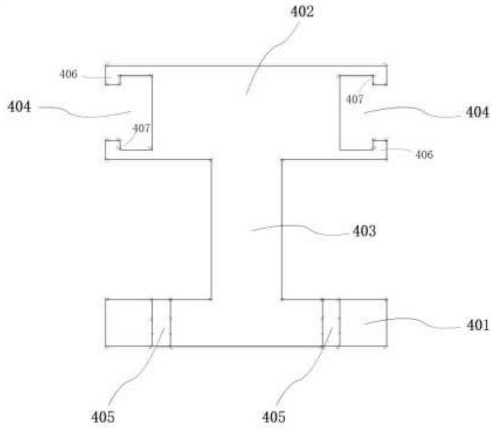
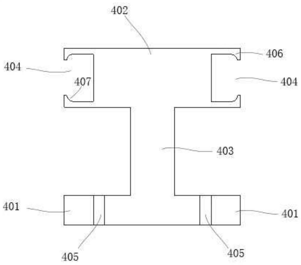
The invention discloses an assembly type bridge beam end telescopic deformation coordination structure and an installation method thereof, and belongs to the technical field of bridge construction. The structure comprises a first beam end and a second beam end which are in gap butt joint; a plurality of first displacement box grooves and second displacement box grooves with symmetrical notches are respectively formed in the side end surfaces of the first beam end and the second beam end along the transverse direction of the gap; a supporting cross beam stretching across the gap is arranged in the first displacement box groove and the second displacement box groove in the depth direction of the box grooves in a sliding mode; and I-shaped steel is fixedly arranged on the supporting cross beam, one end of a top leg plate of the I-shaped steel is connected with the first beam end above each first displacement box groove through a buffer block, and the other end is connected with the second beam end above each second displacement box groove through a buffer block. The structure can play a role in buffering and protecting telescopic deformation of the beam end of the fabricated bridge, is easy to replace and install, and is convenient to maintain during operation.

Description

technical field [0001] The invention belongs to the technical field of bridge construction, and in particular relates to an assembly-type bridge beam end telescopic deformation coordination structure and an installation method thereof. Background technique [0002] At present, prefabricated bridges generally need to install expansion joints at the ends of the beams. The conventional practice is to chisel the ends of the beams at the joints after the prefabricated bridges are installed on site, so as to install expansion devices and pour concrete. The above-mentioned conventional method generally takes about 15 days to complete the construction period, which takes a long time. At the same time, once the traditional telescopic device is damaged, the beam end needs to be destructively removed and replaced, and the maintenance period will take a long time, which will affect the normal traffic. Therefore, it is necessary to study a structure or technology that can meet the requi...

Claims


Application Information

Patent Timeline
Patent Type & Authority Applications(China)
IPC IPC(8): E01D19/06E01D21/00
CPCE01D19/06E01D19/062E01D19/065E01D21/00
Inventor 张建东刘朵冯晓楠熊辉王贤强闫畅苏鑫华
Owner JSTI GRP CO LTD
Learn More