Eureka AIR delivers breakthrough ideas for toughest innovation challenges, trusted by R&D personnel around the world.

Fire-fighting emergency lighting and evacuation indication lighting device and control method thereof

A technology for indicating lighting and fire emergency, which is applied in the direction of lighting devices, lighting devices, parts of lighting devices, etc. It can solve problems such as poor lighting and indicating effects, switching of reserve power, and inability to control and manage, so as to facilitate automatic switching and avoid Confused, beneficial to adjust the effect of use

Pending Publication Date: 2022-01-21
广诺(阳谷)电子科技有限公司
View PDF0 Cites 0 Cited by
  • Summary
  • Abstract
  • Description
  • Claims
  • Application Information

AI Technical Summary

Problems solved by technology

[0003] However, most of the existing fire emergency lighting and evacuation indicating devices are installed inside the corridor respectively. The lighting is installed at the upper end, and the evacuation indicating device is installed at the bottom. Such a split structure requires separate wiring and installation, which is not only cumbersome , and cannot be controlled and managed in a unified manner, which affects the efficiency in an emergency, and the effect is poor, and the existing device needs to provide an additional circuit when supplying power, and cannot directly switch the standby power supply after the normal power supply, and the lighting and indication effects are poor. Improve

Method used


Image

  • Fire-fighting emergency lighting and evacuation indication lighting device and control method thereof
  • Fire-fighting emergency lighting and evacuation indication lighting device and control method thereof
  • Fire-fighting emergency lighting and evacuation indication lighting device and control method thereof

Examples


Embodiment Construction

[0038] The following will clearly and completely describe the technical solutions in the embodiments of the present invention in conjunction with the accompanying drawings in the embodiments of the present invention; obviously, the described embodiments are only part of the embodiments of the present invention, not all embodiments, based on The embodiments of the present invention and all other embodiments obtained by persons of ordinary skill in the art without making creative efforts belong to the protection scope of the present invention.

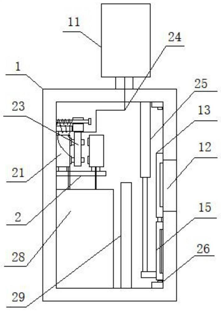
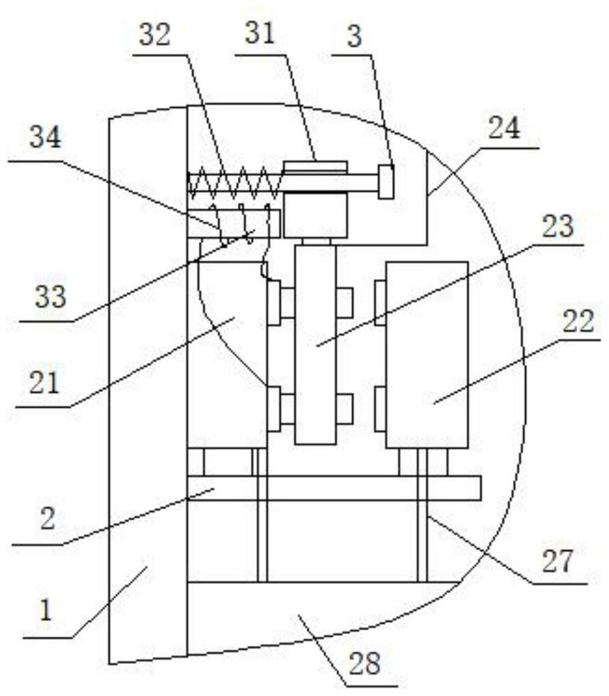
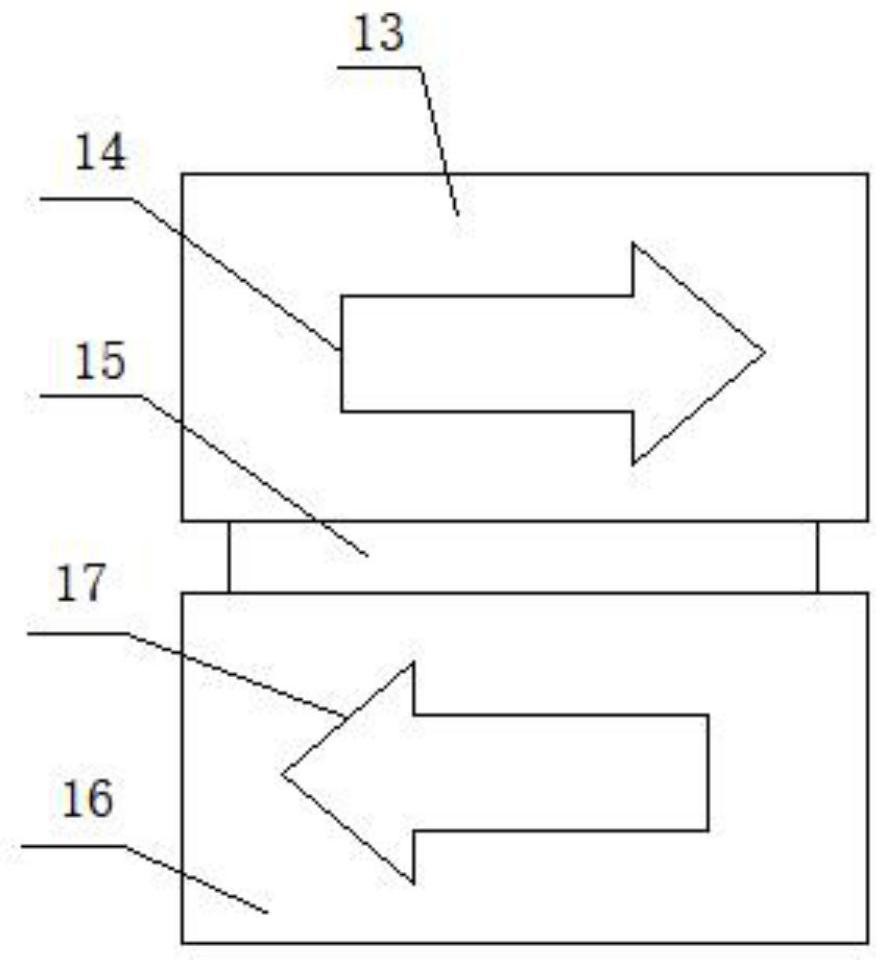
[0039] see Figure 1-4 , a fire emergency lighting and evacuation indicating lighting device and control method, including an outer shell 1, please refer to figure 1 with image 3 The surface of one end of the outer shell 1 is fixedly equipped with a lighting lamp 11, which can be energized for lighting, which is convenient for emergency use. One side surface of the outer shell 1 is provided with an indicating gap 12, and the side surfa...


PUM


Abstract

The invention discloses a fire-fighting emergency lighting and evacuation indication lighting device and a control method thereof. The device comprises an outer shell, a lighting lamp is fixedly installed on the surface of one end of the outer shell, an indication notch is formed in the surface of one side of the outer shell, a first indication plate is slidably connected to the surface of one side of the indication notch, a first indicating plate is fixedly connected to the surface of one side of the outer shell, a right arrow is fixedly sprayed to the surface of one side of the first indicating plate, a connecting plate is fixedly connected to the surface of one side of the first indicating plate, a second indicating plate is fixedly connected to the surface of one end of the connecting plate, a left arrow is sprayed to the surface of the second indicating plate, a mounting frame is fixedly connected to the surface of the other side of the outer shell, a first conductive seat is fixedly mounted on the surface of one end of the mounting frame, and a second conductive seat is fixedly mounted on the surface of the other end of the mounting frame, so that the use convenience and stability can be greatly improved, and the timeliness and safety of emergency control are guaranteed.

Description

technical field [0001] The invention relates to the field of fire-fighting equipment, more specifically, to a fire-fighting emergency lighting and evacuation indicating lighting device and a control method. Background technique [0002] In the current fire management work, in order to ensure the safety and stability of the interior of the corridor, it is necessary to configure fire emergency lighting and evacuation indicating devices, which can carry out emergency lighting and emergency command evacuation when a fire occurs, so as to ensure the safety of people's personal and property. [0003] However, most of the existing fire emergency lighting and evacuation indicating devices are installed inside the corridor respectively. The lighting is installed at the upper end, and the evacuation indicating device is installed at the bottom. Such a split structure requires separate wiring and installation, which is not only cumbersome , and cannot be controlled and managed in a uni...

Claims


Application Information

Patent Timeline
Patent Type & Authority Applications(China)
IPC IPC(8): F21S9/02F21V33/00G09F13/00
CPCF21S9/022F21V33/0076G09F13/00G09F13/005
Inventor 李福岩姜红玉李彪
Owner 广诺(阳谷)电子科技有限公司
Why Eureka
Eureka Blog
Learn More