Fiber-optic gyroscope with optical power self-checking function

A fiber optic gyroscope and optical power technology, which is applied in the direction of Sagnac effect gyroscope, gyroscope/steering sensor equipment, photometry, etc., can solve the application environment that is not suitable for quick start, cannot solve the problem of accurate measurement of optical power, Unable to self-check in real time and other issues, to achieve excellent long-term stability characteristics, high accuracy, and early fault detection

Pending Publication Date: 2022-01-25
上海傲世控制科技股份有限公司
View PDF0 Cites 0 Cited by
  • Summary
  • Abstract
  • Description
  • Claims
  • Application Information

AI Technical Summary

Problems solved by technology

Some fiber optic gyroscopes have a power-on self-test function, but the power-on self-test is only applicable to the moment of power-on and start-up, and cannot perform real-time self-test during work
And the power-on self-test will reduce the start-up time, which is not suitable for the application environment that requires fast start-up, and cannot solve the problem of accurate measurement of optical power
In practical applications, as the core sensor of attitude control and inertial navigation, an instantaneous failure will bring disaster consequences and cause huge losses
In the launch of rockets and satellites, there have been many launch failures or launch delays caused by fiber optic gyro failures

Method used


Image

  • Fiber-optic gyroscope with optical power self-checking function
  • Fiber-optic gyroscope with optical power self-checking function
  • Fiber-optic gyroscope with optical power self-checking function

Examples


Embodiment 1

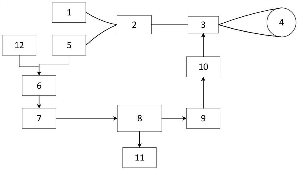
[0030] Such as figure 1 As shown, this embodiment provides a fiber optic gyroscope with an optical power self-test function, including a light source 1, a coupler 2, a Y waveguide 3 and a fiber optic ring 4 connected in sequence, and the fiber optic gyroscope also includes a detector 5 and a reference voltage module 12 , a pre-amplification circuit 6, an AD conversion module 7, a processor 8, a DA conversion module 9, a post-amplification circuit 10 and a power supply for the entire fiber optic gyro, the detector 5 is connected to the coupler 2, the detector 5 and the reference voltage module 12 are connected to the preamplifier circuit 6, the preamplifier circuit 6, the AD conversion module 7, the processor 8, the DA conversion module 9, the postamplifier circuit 10 and the Y waveguide 3 are connected in sequence;

[0031] When in use, the preamplifier circuit 6 subtracts the output voltage of the detector 5 from the reference voltage of the reference voltage module 12, and a...


PUM


Abstract

The invention relates to a fiber-optic gyroscope with an optical power self-checking function, which comprises a light source, a coupler, a Y waveguide and a fiber-optic ring which are connected in sequence, and further comprises a detector, a reference voltage module, a pre-amplification circuit, an AD conversion module, a processor, a DA conversion module, a post-amplification circuit and a power supply for supplying power to the whole fiber-optic gyroscope, the detector is connected with the coupler, the detector and the reference voltage module are both connected with the pre-amplification circuit, and the pre-amplification circuit, the AD conversion module, the processor, the DA conversion module, the post-amplification circuit and the Y waveguide are connected in sequence. Compared with the prior art, the fiber-optic gyroscope not only realizes the function of measuring the angular rate of the fiber-optic gyroscope, but also realizes the function of real-time self-inspection in normal operation of the gyroscope, and has the advantages of early fault discovery, high accuracy and the like.

Description

technical field [0001] The invention relates to the field of optical fiber gyroscopes, in particular to an optical fiber gyroscope with an optical power self-inspection function. Background technique [0002] Gyroscope is an angular rate sensor, a device sensitive to angular motion in relative inertial space, and is currently the main sensor used to determine the spatial motion attitude of moving objects. It can be applied to various fields of sea, land, air and sky. The basic function of the traditional fiber optic gyroscope is to measure the angular rate, and it does not have the function of optical power self-test. Some fiber optic gyroscopes have a power-on self-test function, but the power-on self-test is only applicable to the moment of starting up, and cannot be self-tested in real time during work. Moreover, the power-on self-test will reduce the start-up time, which is not suitable for the application environment requiring fast start-up, and cannot solve the probl...

Claims


Application Information

Patent Timeline
Patent Type & Authority Applications(China)
IPC IPC(8): G01C19/72G01C25/00G01J1/00
CPCG01C19/721G01C25/00G01J1/00
Inventor 李阳白亮虞翔吴海林杨涛施广飞俞岭
Owner 上海傲世控制科技股份有限公司
Why Eureka
Try Eureka