Brass rod surface anti-skid pattern engraving equipment

A brass rod and anti-slip technology, which is applied in the field of anti-slip marking equipment on the surface of brass rods, can solve the problems that brass rods are prone to shaking, and achieve the effect of convenient operation and preventing shaking

Active Publication Date: 2022-01-28
YINGTAN SHENGFA COPPER
View PDF7 Cites 0 Cited by
  • Summary
  • Abstract
  • Description
  • Claims
  • Application Information

AI Technical Summary

Problems solved by technology

[0005] In order to overcome the shortcoming that brass rods are prone to shaking when people use the existing anti-skid marking equipment on the surface of brass rods to mark brass rods, the present invention provides a brass rod surface that can prevent the brass rods from shaking. Anti-slip marking equipment

Method used


Image

  • Brass rod surface anti-skid pattern engraving equipment
  • Brass rod surface anti-skid pattern engraving equipment
  • Brass rod surface anti-skid pattern engraving equipment

Examples


Embodiment 1

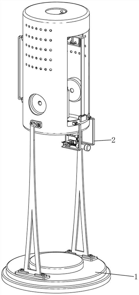
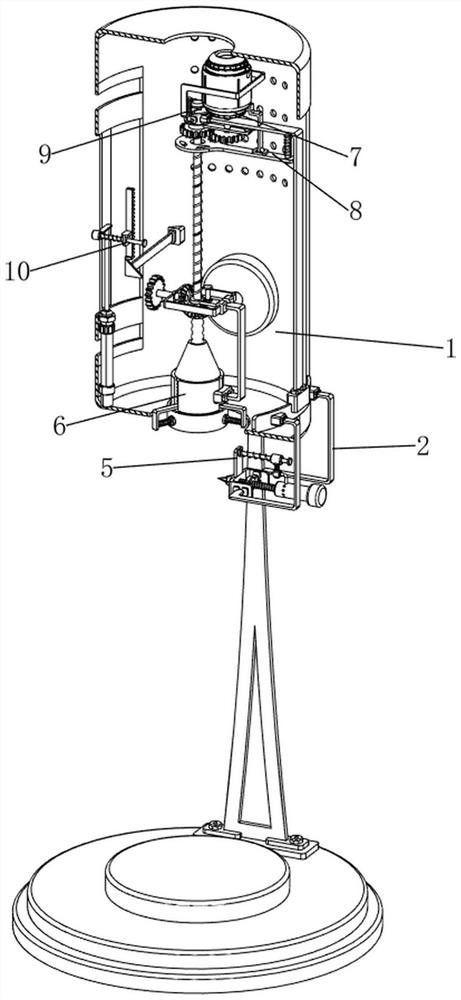
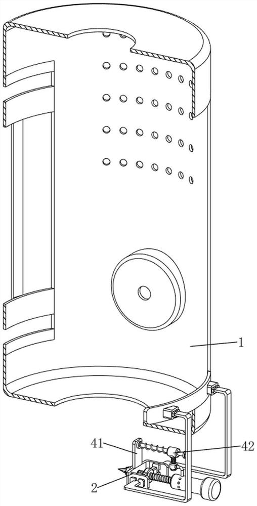
[0040] A device for engraving anti-slip patterns on the surface of brass rods, such as Figure 1-Figure 11As shown, it includes a connecting frame 1, a first connecting rod 2, a nut block 3, a scraper 301, a locking mechanism 4, a scratching mechanism 5 and a rotating mechanism 6, and the upper right side of the connecting frame 1 is welded with the first connecting rod. 2. There is a nut block 3 on the left side of the lower part of the first connecting rod 2, and a thread scraper 301 is provided on the inner side of the nut block 3. After the scraper 301 contacts the brass rod, when the brass rod rotates, it can The copper bar is used for engraving, and the scraper 301 passes through the lower left side of the first connecting rod 2. The first connecting rod 2 is provided with a locking mechanism 4, and the connection frame 1 is provided with a scraping mechanism 5. A rotating mechanism 6 is provided.

[0041] The clamping mechanism 4 includes a second connecting rod 41, a ...

Embodiment 2

[0046] On the basis of Example 1, such as figure 2 , Figure 12 , Figure 13 , Figure 14 , Figure 15 , Figure 16 and Figure 17 As shown, an opening mechanism 7 is also included, and the opening mechanism 7 includes a second driving rod 71, a fourth connecting rod 72, a movable ring 73, a third driving rod 74 and a fourth spring 75, and the left side of the third connecting rod 53 top A second driving rod 71 is provided, a fourth connecting rod 72 is welded on the right side of the upper part of the nut rod 51, and a movable ring 73 is provided on the lower side of the fourth connecting rod 72 slidingly, and a third driving rod 74 is arranged on the right side of the top of the movable ring 73 , the third driving rod 74 can automatically control the output shaft of the motor 61 to reverse when it is in contact with the switch. There is a fourth spring 75 wound on the fourth connecting rod 72 .

[0047] When the third connecting rod 53 moved upward, the third connect...


PUM


Abstract

The invention relates to anti-skid pattern engraving equipment, in particular to brass rod surface anti-skid pattern engraving equipment. The invention aims to provide the brass rod surface anti-skid pattern engraving equipment capable of preventing the brass rod from shaking. The brass rod surface anti-skid pattern engraving equipment comprises a connecting frame, a first connecting rod, a nut block, a pattern scraping device, a clamping mechanism and the like, the first connecting rod is arranged on the upper portion of the right side of the connecting frame, the nut block is arranged on the left side of the lower portion of the first connecting rod, and the pattern scraping device used for engraving the brass rod is arranged on the inner side of the nut block in a threaded mode. The pattern scraping device penetrates through the left side of the lower portion of the first connecting rod, and a clamping mechanism used for preventing the pattern scraping device from moving is arranged on the first connecting rod. A brass rod is placed in a threaded connecting pipe, and the brass rod can be clamped by a clamping rod under the action of the clamping rod, so that the brass rod is prevented from shaking, and anti-slip patterns are prevented from being carved obliquely.

Description

technical field [0001] The invention relates to an anti-slip marking device, in particular to a device for marking an anti-slip on the surface of a brass rod. Background technique [0002] Brass rods are rod-shaped objects made of copper and zinc alloys. They have good mechanical properties and wear resistance. They can be used to manufacture precision instruments, ship parts, gun shells, etc. Anti-skid patterns are printed on the surface of brass rods. It can effectively improve the anti-skid effect of the brass rod, and is convenient for people to take. In the prior art, there are few automatic engraving equipment for brass rods, and most of them are manually used by people to mark the brass rods with a scratcher. [0003] Patent application CN212760647U, the publication date is 20210323, discloses a brass rod surface anti-skid marking equipment, which relates to the field of marking equipment, including a base, the top side of the base is fixedly connected with a support ...

Claims


Application Information

Patent Timeline
Patent Type & Authority Applications(China)
IPC IPC(8): B23D79/10
CPCB23D79/10Y02P70/10
Inventor 徐特张鹏奚君华邹本东何专张佳兵刘刚
Owner YINGTAN SHENGFA COPPER
Why Eureka
Try Eureka