Anti-seismic furniture

A furniture and shock-absorbing device technology, applied in the field of shipbuilding, can solve problems such as high-frequency vibration, severe vibration of furniture, and deformation of furniture, and achieve the effects of reducing vibration amplitude, increasing service life, and improving stability

Active Publication Date: 2022-01-28
GUANGZHOU SHIPYARD INTERNATIONAL LTD
5 Cites 1 Cited by

AI-Extracted Technical Summary

Problems solved by technology

[0002] Ships will be affected by various factors such as sea waves, sea winds and currents during sea navigation and work, so the ship is prone to sway, and the severe sway seriously affects the use of various furniture on the ship. , changes in wind and waves, crests and troughs will continue to collide with the ship's floor, especially when sailing in strong winds and waves, the ship is prone to attack and cause high-frequency vib...

Method used

As a preferred solution, the abutment portion 23 is an abutment plate, and the abutment plate can have a larger contact area, and a rubber layer is provided on the side of the abutment portion 23 away from the sliding bar 24, because the rubber material has a better When the abutting portion 23 collides with the wall, the rubber has a cushioning effect.
As a preferred solution, the junction of the first clamping plate 321 and the second clamping plate 322 is provided with a chamfer 324, because the clamping block 32 is protrudingly arranged on the outer wall of the table 1, in the process of using the table 1 , the body is easy to contact with the block 32, and if a serious collision occurs, the user will be injured. By setting the chamfer 324, the injury of the user can be avoided, and the safety of the earthquake-resistant furniture can be improved.
Concrete, on the side wall of positioning column 21, a plurality of chute 211 is provided through, and one end corresponding chute 211 of slide bar 24 is plugged in positioning column 21 is provided with a plurality of stoppers 241, and stopper 241 is clamped in the chute 211. In this embodiment, the side wall of the positioning column 21 is provided with four sliding grooves 211, and one end of the sliding rod 24 inserted into the positioning column 21 is provided with four stoppers 241 corresponding to the sliding grooves 211. 241 can be clamped in the chute 211 respectively, and the four stoppers 241 can only move along the chute 211 when the sliding rod 24 drives the stopper 241 to move, so that the sliding rod 24 moves in the cavity. No rotation will occur, which improves the stability of the shock absorbing device 2 .
Concrete, two support blocks 26 are at least provided with on the mounting plate 4, support block 26 and positioning column 21 intervals are set, support block 26 is provided with the 3rd mounting hole, and the 3rd mounting hole is provided with limit shaft 27, The end of the telescopic rod 25 away from the abutment plate is rotatably connected with the limiting shaft 27 . In this embodiment, each shock absorbing device 2 is provided with four supporting blocks 26, and every two supporting blocks 26 form a group, and the two groups of supporting blocks 26 are symmetrically arranged on both sides of the positioning column 21 respectively, and each supporting block The side wall of 26 is provided with the 3rd mounting hole, and the 3rd mounting hole between every group of support block 26 is installed limit shaft 27, and tele...

Abstract

The invention relates to anti-seismic furniture which comprises a table, damping devices and mounting plates; the mounting plates are arranged on the outer side wall of the table; each damping device comprises a positioning column, a first spring and an abutting part; the positioning column is arranged on the corresponding mounting plate, and a cavity is formed in each positioning column; the abutting part is arranged on one side of the corresponding positioning column at interval, and a sliding rod is arranged on one side of each abutting part; the end, away from the corresponding abutting part, of the sliding rod is slidably arranged in the cavity, each abutting part is rotationally connected with at least two telescopic rods, the ends, away from the abutting parts, of the telescopic rods are connected with the mounting plates, the first spring is arranged in each cavity, one end of each first spring is connected with the corresponding mounting plate, and the other end of each first spring is connected with the corresponding sliding rod; and each first spring always drives the corresponding abutting part to move towards one side far away from the corresponding mounting plate. According to the anti-seismic furniture, the furniture can be prevented from deforming in the vibration process, articles placed on the table are not prone to displacement, the articles are not prone to collision, and thus the stability of the furniture is improved, and the service life of the furniture is prolonged.

Application Domain

Cabin tablesStorm guards

Technology Topic

Earthquake resistantEngineering +2

Image

  • Anti-seismic furniture
  • Anti-seismic furniture
  • Anti-seismic furniture

Examples

  • Experimental program(1)

Example Embodiment

[0027] In order to make the technical problem solved by the present invention, the technical solution and the technical effects achieved are more clear, and the technical solutions of the embodiments of the present invention will be further described in connection with the accompanying drawings, which will be described in detail. Part of embodiments, not all embodiments. Based on the embodiments of the present invention, those skilled in the art are in the range of the protected by the present invention without creative labor premistence.
[0028] In the description of the present invention, the term "connected", "connection", "fixed", unless otherwise specified, "connected", "fixed", for example, may be a fixed connection, or a detachable connection, or integral However, it can be a mechanical connection or an electrical connection; it can be directly connected, or the intermediate medium can be indirectly connected, which may be a communication between two elements or two components. Relationship. The specific meaning of the above terms in the present invention will be appreciated to those skilled in the art.
[0029] In the present invention, unless otherwise expressly specified and defined, the first feature "upper" or "lower" or "lower" may include direct contact between the first and second features, and may include first and second features. It is not directly in contact with additional feature between them. Moreover, the first feature "above", "above" and "upper" include the first feature to the second feature is directly above and obliquely, or only means that the first feature level is higher than the second feature. The first feature is in the second feature "under", "below" and "below" include the first feature to the second feature is below and obliquely, or only the first feature level height is less than the second feature.
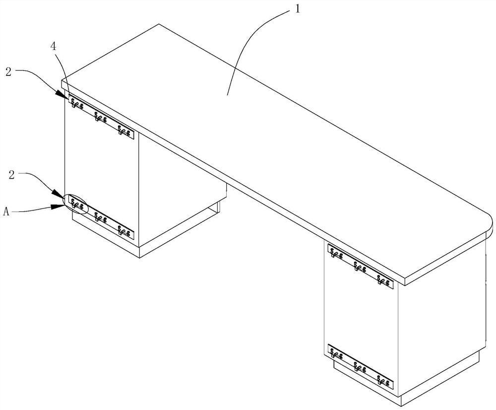
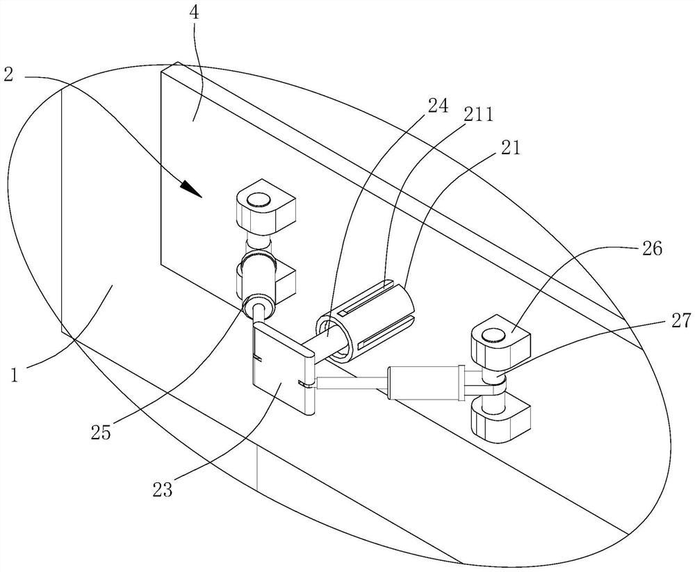
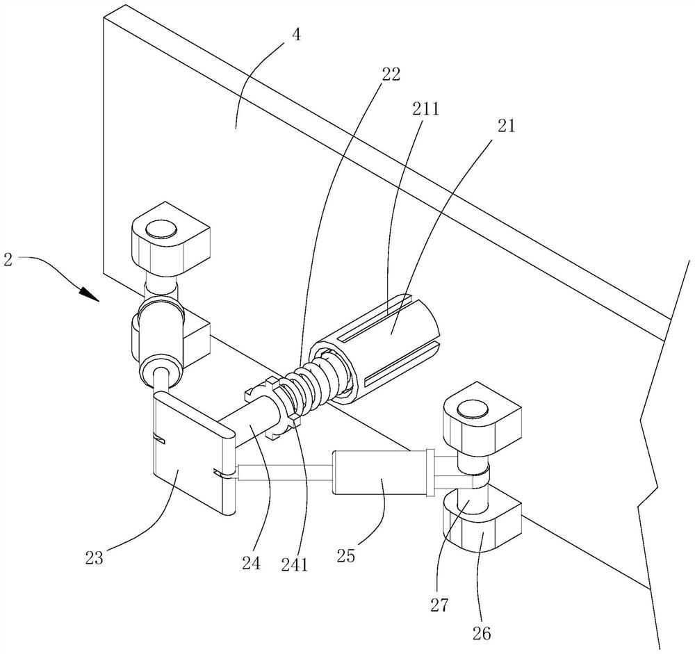
[0030] Nautical cabin regions often have furniture for placing a computer and store an office. The currently used ship furniture is directly fixed to the hull, which is prone to vibration. It is easy to cause displacement of items to be placed inside. It is easy to cause the furniture itself, so it needs A ship with a seismic function is provided on the ship to prevent the above problems. Therefore, the structure of the seismic furniture of the present invention will be described in detail with reference to the specific embodiments.
[0031] like Figure 1 to 3As shown, the seismic furniture of the present invention includes a table 1, a mounting plate 4, and a damping device 2, and the mounting plate 4 is disposed on the outer wall of the table 1, and the damper device 2 includes a positioning post 21, a first spring 22 and an abutment portion. 23. The positioning post 21 is disposed on the mounting plate 4, and the inner portion of the positioning post 21 is disposed, and the abutting portion 23 is disposed on one side of the positioning post 21, and the side of the abutting portion 23 is provided with a slider 24, the slider bar. The 24th end of the abutting portion 23 is slid in the cavity, and the abutting portion 23 is rotated from the at least two telescopic rod 25, and the retracting rod 25 is connected to the mounting plate 4 from the upper end of the abutting portion 23, and the first spring 22 is set. In the cavity, one end of the first spring 22 is connected to the mounting plate 4, and the other end is connected to the slider 24, and the first spring 22 always drives the abutment portion 23 toward the movement of the mounting plate 4. It will be appreciated that a plurality of mounting plates 4 are provided on the side walls of the table 1 close to the ship wall, and a plurality of shock absorbers 2 can be provided on each mounting plate 4, when contact between the table 1 and the ship, The connecting portion 23 is subjected to a force to apply a pressure to the first spring 22, and the first spring 22 is deformable, and the first spring 22 is absorbed in the deformation process, and at the same time The portion 23 acts at the first spring 22 deformation process to cancel the elastic force of the first spring 22, and press the telescoping rod 25, and the telescoping rod 25 is deformation in the displacement process and the abutting portion 23 is active. Absorbed the effect of re-challenge again. After double absorption of the force by the first spring 22 and the telescoping rod 25, the action force of the table 1 becomes very small, in which the table 1 will generate a dramatic vibration, so that the furniture on the ship is not It is necessary to fix directly on the hull to avoid the fact that the furniture has a deformation during the vibration. And during the ship navigation process, the items placed on the table 1 are not prone to displacement, and there is not easy to collide between items, thereby improving the stability of furniture, increasing the life of furniture.
[0032] In this embodiment, the table 1 is provided with four mounting plates 4 adjacent to the side surface of the ship wall, and the four mounting plates 4 have a rectangular four-angle distribution, and three damping devices 2 are provided on each mounting plate 4, so that the ship During the vibration, the four-angle distribution damper device 2 can uniformly withstand the force and the absorption force, and a plurality of damping devices 2 can be improved on each mounting plate 4 to improve the seismic effect of the table 1. In other embodiments, the mounting plate 4 on the table 1 may also be provided, three or six, etc., the number is set according to the actual needs, and each mounting plate 4 can also be provided with the damping device 2 according to actual needs. quantity.
[0033] In other embodiments, the furniture on the ship also includes a chair, a bookcase and a wardrobe, etc., can also be provided in the above furniture, and the damper device 2 can be provided by setting the damping device 2 to cause furniture and ship wall due to ship vibration. Thereby collisions, can improve the life of furniture.
[0034] Specifically, a plurality of chutes 211 are arranged on the side wall of the positioning column 21, and the sliding rod 24 is inserted with one end of the positioning column 21, corresponding to the slot 211, and a plurality of limit pieces 241, the limit piece 241 card Inside the slot 211. In the present embodiment, four chutes 211 are provided on the side wall of the positioning post 21, and four restricted grooves 211 are provided with four limit pieces 241, limit parts in the sliding rod 24 inserted at one end in the positioning post 21. 241 can be directly coupled to the slot 211, and the sliding rod 24 is moved during the movement of the restricted member 241, and the four restricted members 241 can only move along the slide 211, so that the slider 24 is in the middle of the cavity. The stability of the shock absorbing device 2 is not rotated.
[0035] When the shock occurs, in order to reduce the offset of the position as much as possible, the abutting portion 23 abuts on the wall of the ship such that when the ship occurs, the abutting portion 23 can be quickly contacted with the wall, and The abutting portion 23 shifts the force to the first spring 22 and the telescopic rod 25, and improves the damping effect of the damping device 2.
[0036] As a preferred embodiment, the abutting portion 23 is an abut plate, and the abutting plate may have a large contact area, and a rubber layer is provided on one side of the abutting portion 23 away from the slider 24, since the rubber material has better elasticity, When the abutting portion 23 collides with the wall, the rubber has a buffer effect.
[0037] Specifically, at least two support blocks 26 are provided on the mounting plate 4, the support block 26 is disposed at intervals of the positioning post 21, and the support block 26 is provided with a third mounting hole, the third mounting hole is provided with a finite axis 27, telescopic rod 25. Turn the connection to the limit shaft 27 from one end of the abutting plate. In this embodiment, each of the damping means 2 is provided with four support blocks 26, each of the two support blocks 26, and the two sets of support blocks 26 are respectively symmetrically disposed on both sides of the positioning post 21, in each support block. The third mounting hole is opened on the side wall of 26, and the third mounting hole between each set of support blocks 26 is mounted on the finite axis 27, and the telescopic rod 25 is rotated from the upper end of the abutting plate to the limit shaft 27, so that in the telescopic When the rod 25 is squeezed by the abutting plate, the retracting rod 25 and the limit shaft 2 have a rotationally adjusted space, and increase the service life of the telescopic rod 25. Further, the two telescopic rods 25 are symmetrically disposed on opposite sides of the abutting plate, and the two telescopic rods 25 and the mounting plate 4 are connected to form a triangular structure, and the triangular structure can improve the stability of the entire shock absorbing device 2.
[0038] Specifically, the seismic furniture also includes a locking apparatus 3, and the locking apparatus 3 includes a block 32, a fixing frame 31, and a lock assembly 33, and the table 1 is also provided with a drawer 11, and the fixing frame 31 is disposed on the side wall of the table 1. And adjacent to the drawer 11, the block 32 is rotated from the holder 31, and the block 32 is provided with the first mounting hole 323 from one end of the fastener 31, and the drawer 11 corresponding to the first mounting hole 323 is provided with a second mounting hole. The lock assembly 33 is disposed in the first mounting hole 323 and the second mounting hole, and the lock assembly 33 can lock the card block 32 to the drawer 11. In this embodiment, if Figure 4 to 7 As shown, there is a plurality of drawers 11 on the table 1, and the locking device 3 includes a block 32, a fixing frame 31, and a locking assembly 33, and the mount 31 is disposed on the outer wall of the table 1, and the fixing frame 31 is located close to The position of the drawer 11, one end of the block 32 is rotated from the holder 31, and the other end of the block 32 may be away from the fixing frame 31 away from or near the drawer 11, the lock assembly 33 is fixed to the first mounting hole 323 and the second mounting hole. Inside, and when the drawer 11 is locked, the block 32 abuts on the side wall of the drawer 11, and the lock assembly 33 locks the card block 32 and the drawer 11; the drawer 11 is taken in the case of the article, the card block 32 is driven The lock assembly 33 exits the second mounting hole and is located away from the drawer 11, avoiding interference with the card block 32 when the drawer 11 is opened, so that on the ship, it can control the drawer 11 to open or lock, not due to the ship shaking Leading to the opening of the drawer 11.
[0039] Specifically, the wall surface of the first mounting hole 323 has a mounting groove 3231, and the lock assembly 33 includes a binding ring 331, a slide ring 332, a second spring 333, and a fixed column 334, and a hindered ring 331 fixedly disposed in the first Inside the mounting hole 323, the fixing post 334 slides in the bonding ring 331, the sliding ring 332 slides in the mounting groove 3231 and fixed to the outer side wall of the fixing post 334, and the binding ring 331 is close to one end of the sliding ring 332. Tooth teeth. 3311, the sliding ring 332 is provided with a card slot 3321, and the second spring 333 is disposed within the mounting groove 3231, and one end of the second spring 333 is connected to the groove wall of the mounting groove 3231, and the other end is connected to the sliding ring 332, fixed. The column 334 extends to the second mounting hole and is connected to the limit plate 335, and the restricted plate 335 abuts on the inner side wall of the drawer 11 and the other end extends to the first mounting hole 323. In this embodiment, one end of the second spring 333 is connected to the groove wall of the mounting groove 3231, and the other end is connected to the sliding ring 332, and the second spring 333 always drives the sliding ring 332 to rotate in the first direction while providing the sliding ring 332. The support force in the second direction is to complete the card slot 3321 and the snap teeth 3311, and the fixed column 334 extends to one end of the first mounting hole 323 and the pull block 336. When the drawer 11 is taken out, press the pull block 336, and the pull block 336 is pulled to the fastening column 334 to the force direction displacement, the fixing post 334 is driven during the displacement, and the sliding ring 332 overcomes the support for the second spring 333. When moving away from the bonding ring 331, when the sliding ring 332 is moved to a certain position, the card slot 3321 on the sliding ring 332 exits the tumo 3311 on the binding ring 331, and then the ring 331 will lose the binding force of the sliding ring 332, At this time, the pull block 336 can be rotated, the pull block 336 is pulled to drive the fixed column 334 and the restricted sheet 335 fixed to the fixed column 334 and the sliding ring 332 to overcome the torque of the second spring 333 in the second direction. When the seat plate 335 is rotated to a suitable position, the restricted plate 335 loses the binding of the block 32, and the block 32 is lost after the locking function of the drawer 11 can open the drawer 11, and then remove the item in the drawer 11. The drawer 11 can be locked by the lock assembly 33, thereby avoiding the ship navigation, resulting in the opening of the drawer 11 due to shaking, so that the inside of the drawer 11 is lost, and the fixation effect of the furniture is increased, improved The safety of the equipment and equipment is placed in furniture.
[0040] In this embodiment, the mounting frame 31 is disposed on the outer side wall of the table 1, and the outer side wall and the drawer 11 are arranged at an angle, and the block 32 is "L" type structure, the block 32 includes a first card with an angle setting. The plate 321 and the second card plate 322, the first card plate 321 is rotated to the holder 31, and the second card plate 322 is used to prevent the drawer 11 from being separated from the table 1 such that the first card plate 321 and the second card plate 322 The angle can better with the outer side wall with the drawer 11 opening, the structure is beautiful and the space is saved within the table 1.
[0041] As a preferred embodiment, the connection at the first board 321 and the second card plate 322 is provided with a reverse angle 324, since the block 32 is protruding on the outer side of the table 1, in the process of using the table 1, the body is easy Contact with the card block 32, if a serious collision can cause the user to be injured, by setting the inverted angle 324, the person is injured and the safety of the seismic furniture can be avoided.
[0042] Specifically, the inner side wall of the drawer 11 is formed along the second mounting hole ring, and the restricted plate 335 is in contact with the center of the limit slot and can rotate about the center of the second mounting hole. In the present embodiment, the restricted groove is a sector structure, and the radius length of the sector restricted groove is provided according to the length of the limit plate 335, and the sidewall of the fan-shaped bit groove can be turned on when the restricted restricted plate 335 is rotated. 335 is limited to avoid the use of personnel transition to pull the block 336, thereby affecting the service life of the second spring 333.
[0043] As a preferred embodiment, the handle 111 is provided at the opening end of each of the drawers 11, and the handle 111 can be convenient to the player drawer 11.
[0044] In the description of this article, it is to be understood that the terms "upper", "lower" orientation is based on the orientation or positional relationship shown in the drawings, which is only for ease of description and simplification, rather than indication or hints. The referred to the device or element must have a specific orientation, constructed and operated in a particular orientation, and thus is not to be construed as limiting the invention.
[0045] In the description of this specification, a description of the reference terms "an embodiment" means that the specific features, structures, materials, or features of the present invention are included in at least one embodiment or example of the present invention. In the present specification, a schematic representation of the above terms is not necessarily referred to as the same embodiment.
[0046] Further, it should be understood that while the present specification be described in terms of embodiments, but not every embodiment contains only a separate aspect, this narrative description only for the sake of clarity, those skilled in the specification as a whole should The technical solutions in each embodiment may also be combined, and other embodiments which will be appreciated by those skilled in the art can be formed.
[0047]The technical principles of the present invention are described above in connection with specific embodiments.These descriptions are intended to explain the principles of the present invention without the limitation of the scope of the invention.Based on the explanation here, those skilled in the art do not need to pay creative labor to prioritize other embodiments of the present invention, which will fall within the scope of the invention.

PUM

no PUM

Description & Claims & Application Information

We can also present the details of the Description, Claims and Application information to help users get a comprehensive understanding of the technical details of the patent, such as background art, summary of invention, brief description of drawings, description of embodiments, and other original content. On the other hand, users can also determine the specific scope of protection of the technology through the list of claims; as well as understand the changes in the life cycle of the technology with the presentation of the patent timeline. Login to view more.

Similar technology patents

Composite metal tile and its making process

InactiveCN1970961Areduce vibrationSolve the noise
Owner:天津以道新型建材有限公司

Balance shock absorbing device for meal delivering robot

InactiveCN106584514Areduce vibration
Owner:ZHEJIANG JINYUAN IND CO LTD

Method and device for compensating torque of single-rotor compressor

Owner:佛山市顺德区和而泰电子科技有限公司

Power generation unit of integrated gearbox design for aircraft engine

ActiveUS20150311770A1undesirable increase of be suppressreduce vibration
Owner:KAWASAKI HEAVY IND LTD

Classification and recommendation of technical efficacy words

  • reduce vibration
  • avoid deformation

Fracturing manifold quick connecting device

Owner:YANTAI JEREH PETROLEUM EQUIP & TECH

Startup control method of brushless DC motor

InactiveUS20060132075A1reduce vibrationcurrent be restrict
Owner:SAMSUNG ELECTRONICS CO LTD

Integrated quiet Motorized Roller Shade System

InactiveUS20100307701A1reduce vibrationreduce transmission of sound
Owner:PETERSON THOMAS

Profiled spacers for insulation glazing assembly

InactiveUS6339909B1high heat insulate characteristicavoid deformation
Owner:TECHNOFORM CAPRANO & BRUNNHOFER

Method for welding thin steel plate

Owner:浙江东海岸船业有限公司

Bored pile construction method for reinforcing cage framework layered installation

InactiveCN103615001AAvoid hitting the hole wallavoid deformation
Owner:NINGBO SHENGHONG CONSTR ENG

Touch panel and touch display device

InactiveCN105353910Aavoid deformation
Owner:INTERFACE OPTOELECTRONICS SHENZHEN +1
Why Eureka
Try Eureka