


Quick Research
Generate reliable direction feasibility study reports for your R&D in just a few steps.

Technical Q&A
Discover and master advanced knowledge NOW. Basics, ideas, possibilities, all at once.

Find Solutions
As an expert in R&D theories, this can generate solutions to your technical problems instantly.

Evaluate Feasibility
Analyze your overall solution with one click, know your potential R&D risks in advance.

Monitor Landscape
Get weekly tech updates, stay abreast of the latest tech innovations and key insights.
Plastic mesh bag label pasting device
A label sticking and mesh bag technology, which is applied in the field of plastic mesh bag label sticking devices, can solve the problems of dislocation, film-type labels are prone to dislocation, etc., and achieves the effects of convenient collection, convenient sticking, and improved efficiency.
- Summary
- Abstract
- Description
- Claims
- Application Information
AI Technical Summary
Problems solved by technology
Method used
Image

Examples
Embodiment 1
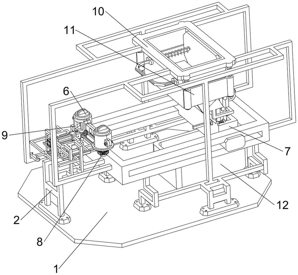
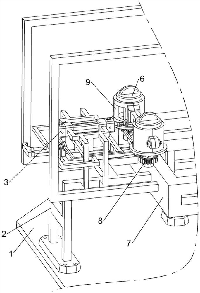
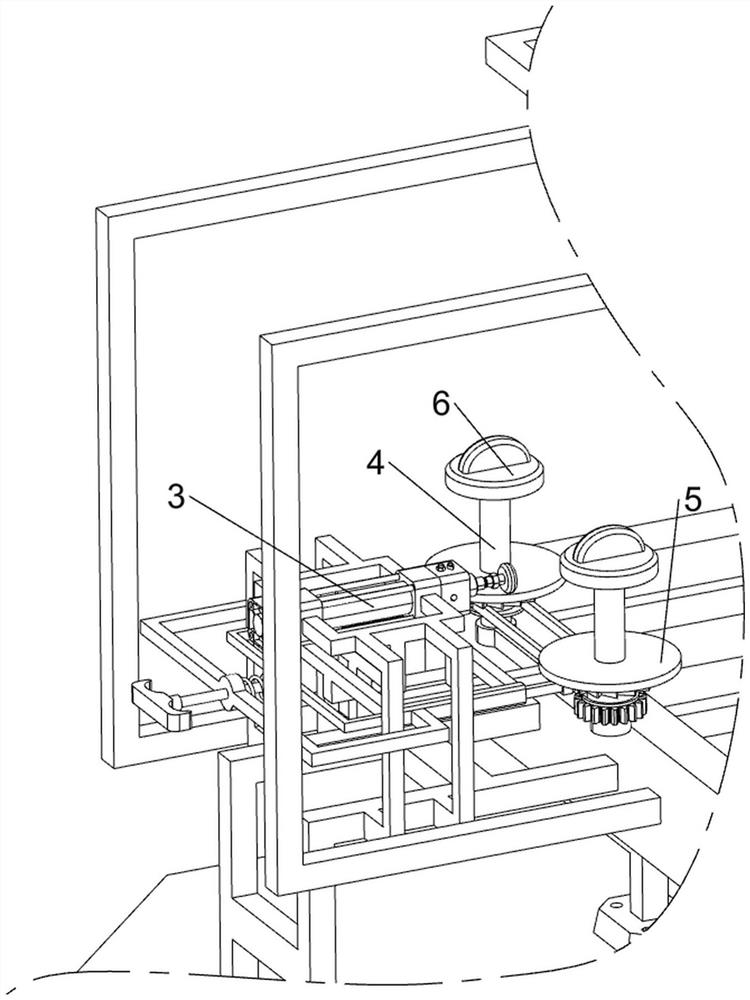
[0039] A plastic mesh bag label sticking device, such as Figure 1-8 As shown, it includes a base plate 1, a first support frame 2, a cylinder 3, a rotating shaft 4, a support plate 5, a cover 6, a pushing mechanism 7 and a transmission mechanism 8, and the bottom of the base plate 1 is provided with an anti-slip rubber pad, which is not easy to slip. 1 The left side of the top is provided with a first support frame 2, the middle part of the upper right side of the first support frame 2 is equipped with a cylinder 3, and the front and rear sides of the upper right side of the first support frame 2 are rotatably provided with a rotating shaft 4 , the middle and lower parts of the two rotating shafts 4 are provided with a support plate 5, and the tops of the two rotating shafts 4 are all threaded and detachably mounted with a cover 6, and the two supporting plates 5 are all located at the lower part of the right side of the telescopic rod of the cylinder 3, A pusher mechanism 7 ...
Embodiment 2
[0046] On the basis of Example 1, such as figure 1 with Figure 9 As shown, it also includes a discharge mechanism 10, and the discharge mechanism 10 includes a fourth support frame 100, a discharge box 101, a pull rod 102, a pressing plate 103 and a second return spring 104, and the right side of the top of the base plate 1 is welded with a fourth Support frame 100, the second support frame 70 and electric slide rail 71 are all connected with the 4th support frame 100, and the upper part on the right side of the 4th support frame 100 is equipped with discharging box 101, and discharge box 101 is positioned at electric slide rail 71 The upper part, and the upper part on the left side of the discharge box 101 is provided with a pull rod 102 slidingly, and the right side of the pull rod 102 is provided with a pressing plate 103. The front and rear sides of the outside of the right part of 102 are all covered with a second return spring 104, and the two ends of the second return...
Embodiment 3
[0049] On the basis of Example 2, such as figure 1 , Figure 10 , Figure 11 , Figure 12 with Figure 13 As shown, a blanking mechanism 11 is also included, and the blanking mechanism 11 includes a first clamping plate 110, a second clamping plate 111, a connecting plate 112, a limiting plate 113, a third return spring 114, a first return force spring 115, a support block 116, guide rod 117, the second return force spring 118, swash plate 119, connecting rod 1110, clamping block 1111 and clamping plate 1112, slide block 72 inner left sliding type is provided with the first clamping plate 110, the first clamping plate 110 and slide block The damping coefficient between 72 is relatively large, and the inner right side of the slider 72 is slidingly provided with a second splint 111, the second splint 111 is in contact with the right side of the first splint 110, and the upper sliding type of the inner right side of the slider 72 A limiting plate 113 is provided on the ground, ...
PUM
 Abstract
Description
Claims
Application Information
 - R&D Engineer
- R&D Manager
- IP Professional
- Industry Leading Data Capabilities
- Powerful AI technology
- Patent DNA Extraction
Browse by: Latest US Patents, China's latest patents, Technical Efficacy Thesaurus, Application Domain, Technology Topic, Popular Technical Reports.
© 2024 PatSnap. All rights reserved.Legal|Privacy policy|Modern Slavery Act Transparency Statement|Sitemap|About US| Contact US: help@patsnap.com