

Combustion chamber test device of aviation gas turbine and test method thereof
An aviation gas turbine and test device technology, which is applied in the direction of gas turbine engine testing, measuring equipment, engine testing, etc., can solve the problems of increasing the difficulty of the work of the staff, inconvenient movement, inconvenient replacement, etc., so as to facilitate the storage and unfolding of the runners , Conducive to installation, increase the effect of stability
Pending Publication Date: 2022-01-28
沈阳航所动力设备有限公司
View PDF0 Cites 0 Cited by
- Summary
- Abstract
- Description
- Claims
- Application Information
AI Technical Summary
Problems solved by technology
[0003] In the research of the global flow afterburning cycle engine technology, all the hydrogen and helium flow through the pre-combustion chamber are burned once to drive the turbine, and then enter the combustion chamber for secondary combustion.
Method used
View moreImage
Smart ImageViewing Examples

Examples
 PUM
 Abstract
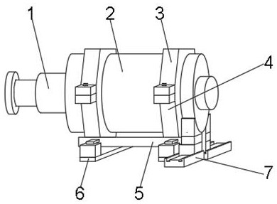
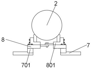
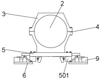
The invention discloses a combustion chamber test device of an aviation gas turbine and a test method thereof. The combustion chamber test device comprises an engine head, wherein an engine body is mounted at the output end of the engine head, and an upper mounting plate and a first bottom plate are arranged at the top of the engine body, a first bottom plate which is arranged at the bottom of a connecting plate, wherein a positioning rod is hinged to one end of the top of the first bottom plate. The device has the beneficial effects that the motor drives the two-way threaded rod to rotate, the two-way threaded rod can drive the guide block and the adjusting plate to move synchronously, the guide block can drive the rotating wheel to rotate through the first transmission rod and the mounting block in the moving process, the rotating wheel is convenient to store and unfold, in the storage process, the adjusting plate can drive the positioning rod of the through hole of the first supporting plate to rotate, the positioning block is inserted into the clamping groove of the fixing plate, the top of the positioning block can be attached to the bottom of the second sliding block, the second sliding block can be fixed through the positioning block, and thus supporting and fixing of the connecting plate are achieved.
Description
technical field [0001] The invention relates to a test device, in particular to a combustion chamber test device of an aviation gas turbine and a test method thereof, belonging to the technical field of the combustion chamber test of the aviation gas turbine. Background technique [0002] Aviation is a complex and strategic human activity, which refers to the flight and navigation activities of aircraft in the earth's atmosphere and air space. The combustion chamber is a device in which fuel or propellant is burned to generate high-temperature gas. It is a durable Combustion equipment made of high-temperature alloy materials, the space between the top of the piston and the cylinder head after the piston reaches the top dead center, the fuel is burned in this room, it is an important part of the gas turbine engine, ramjet engine and rocket engine, composed of diffuser , Combustion chamber shell, flame cylinder, fuel nozzle, ignition device, divided into single-tube combustion...
Claims
Login to View More Application Information
Patent Timeline
 IPC IPC(8): G01M15/14G01M15/02
CPCG01M15/14G01M15/02
Inventor韩崇福卞鈺铁克田金龙苏彬
Owner沈阳航所动力设备有限公司