Robot track presetting mechanism and method based on Internet of things
An Internet of Things and robotics technology, applied in manipulators, manufacturing tools, etc., can solve problems affecting production efficiency, low efficiency, and high handling costs
- Summary
- Abstract
- Description
- Claims
- Application Information
AI Technical Summary
Problems solved by technology
Method used
Image
Examples
Embodiment 1
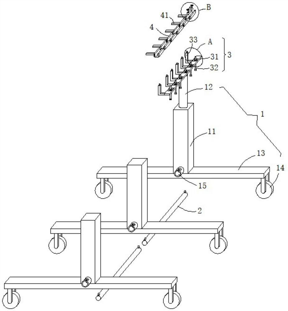
[0033] see Figure 1-4 , this embodiment provides a robot track preset mechanism and preset method based on the Internet of Things, including several support mechanisms 1, adjustment mechanisms 3 and several tracks 4, and two adjacent support mechanisms 1 are detachably connected by connecting rods 2 , the number of support mechanisms 1 can be set according to the use support requirements, and then connected by connecting rods 2 to form a transmission frame for supporting the adjustment mechanism 3 and the track 4.
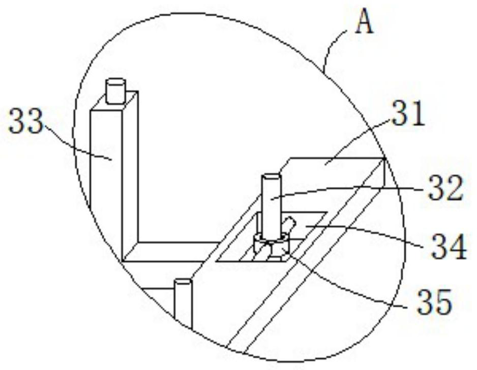
[0034] The support mechanism 1 includes a support column 12, and the adjustment mechanism 3 includes a support beam 31. The support beam 31 is rotatably arranged on the top of the support column 12, and the support beam 31 of the adjustment mechanism 3 is emptied through the support column 12, so that the adjustment mechanism 3 supports the track. 4 use.
[0035] The supporting crossbeam 31 is provided with several adjusting holes 34 evenly spaced, and the inside...
Embodiment 2
[0042] see Figure 1-2 , further improvements have been made on the basis of Example 1:
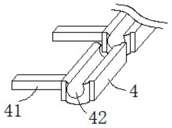
[0043] In order to avoid affecting the adjustment of the travel path of the track 4 when two adjacent tracks 4 are rotated and fitted together, one end of the track 4 is provided with an arc-shaped protrusion, and the other end of the track 4 is provided with an arc-shaped groove. The arc-shaped protrusions and the arc-shaped grooves are rotated and fitted between two adjacent rails 4. No matter how the angle of the rails 4 is adjusted, the arc-shaped protrusions will rotate and fit with the arc-shaped grooves. Gaps and hesitation occur for easy adjustment operations.
[0044] In addition, the internal cross-section of the chute 42 is a circular structure, on the one hand, it is convenient for the ball-type rotating seat 54 to roll along the inside of the chute 42, and on the other hand, it can prevent the ball-type rotating seat 54 from sliding from the chute 42 while rolling. The open...
Embodiment 3
[0049] see figure 1 and Figure 5 , further improvement is made on the basis of embodiment 2:
[0050] The bottom ends of the front and rear side walls of the square column 11 are fixedly provided with connecting seats 15, and the connecting seats 15 on the opposite side walls of the square columns 11 of the two adjacent support mechanisms 1 are respectively inserted into the axial ends of the connecting rod 2, and the The connecting rod 2 is inserted into two opposite connecting seats 15 to connect two adjacent supporting mechanisms 1 .
[0051] In order to avoid the separation of the supporting mechanism 1 that is connected together, an L-shaped clamping gap is provided on the radial side wall of the connecting seat 15, and L is provided with a clamping groove from the inner side wall of the clamping gap, and the connecting rod 2 is radially connected to both ends of the connecting rod 2. The side walls are fixed with a limit block 21. After inserting the end of the connec...
PUM
 Abstract
Description
Claims
Application Information
 - R&D
- Intellectual Property
- Life Sciences
- Materials
- Tech Scout
- Unparalleled Data Quality
- Higher Quality Content
- 60% Fewer Hallucinations
Browse by: Latest US Patents, China's latest patents, Technical Efficacy Thesaurus, Application Domain, Technology Topic, Popular Technical Reports.
© 2025 PatSnap. All rights reserved.Legal|Privacy policy|Modern Slavery Act Transparency Statement|Sitemap|About US| Contact US: help@patsnap.com


