Optical lens, camera module and electronic equipment

An optical lens and lens technology, applied in optics, optical components, instruments, etc., can solve the problems of poor manufacturability, degradation of image quality, and miniaturization of difficult and ultra-wide-angle camera lenses. The effect of miniaturized design

Active Publication Date: 2022-02-01
JIANGXI JINGCHAO OPTICAL CO LTD
View PDF4 Cites 2 Cited by
  • Summary
  • Abstract
  • Description
  • Claims
  • Application Information

AI Technical Summary

Problems solved by technology

Among them, the improvement of the portability of electronic equipment puts forward higher requirements for the thickness of the camera lens. At the same time, the use of chips with a large image surface has become an inevitable trend. The support leads to the decline of imaging image quality and deterioration of manufacturability; especially for ultra-wide-angle camera lenses, because conventional ultra-wide-angle camera lenses use a quasi-symmetrical structure in the middle of the aperture, it is difficult to fully miniaturize the ultra-wide-angle camera lens, so the improvement The thinness and lightness of the ultra-wide-angle camera lens and the problems of maintaining good imaging quality need to be solved urgently

Method used


Image

  • Optical lens, camera module and electronic equipment
  • Optical lens, camera module and electronic equipment
  • Optical lens, camera module and electronic equipment

Examples


no. 1 example

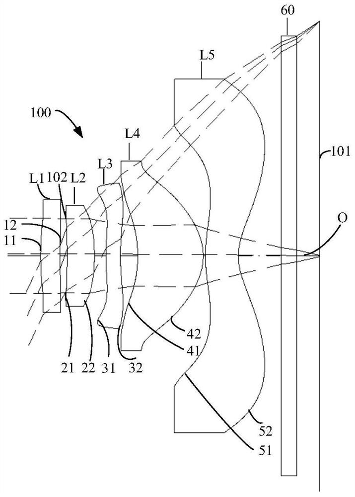
[0100] The structural diagram of the optical lens 100 disclosed in the first embodiment of the present application is as follows figure 1 As shown, the optical lens 100 includes a first lens L1, a diaphragm 102, a second lens L2, a third lens L3, a fourth lens L4, a fifth lens L5, an infrared Filter 60. Wherein, the first lens L1 has positive refractive power, the second lens L2 has positive refractive power, the third lens L3 has positive refractive power, the fourth lens L4 has positive refractive power, and the fifth lens L5 has negative refractive power.

[0101] Further, the object side 11 of the first lens L1 is convex at the near optical axis O, and the image side 12 of the first lens L1 is concave at the near optical axis O; the object side 21 and image side 22 of the second lens L2 are at The near optical axis O is concave and convex respectively; the object side 31 and image side 32 of the third lens L3 are respectively convex and concave at the near optical axis O;...

no. 2 example

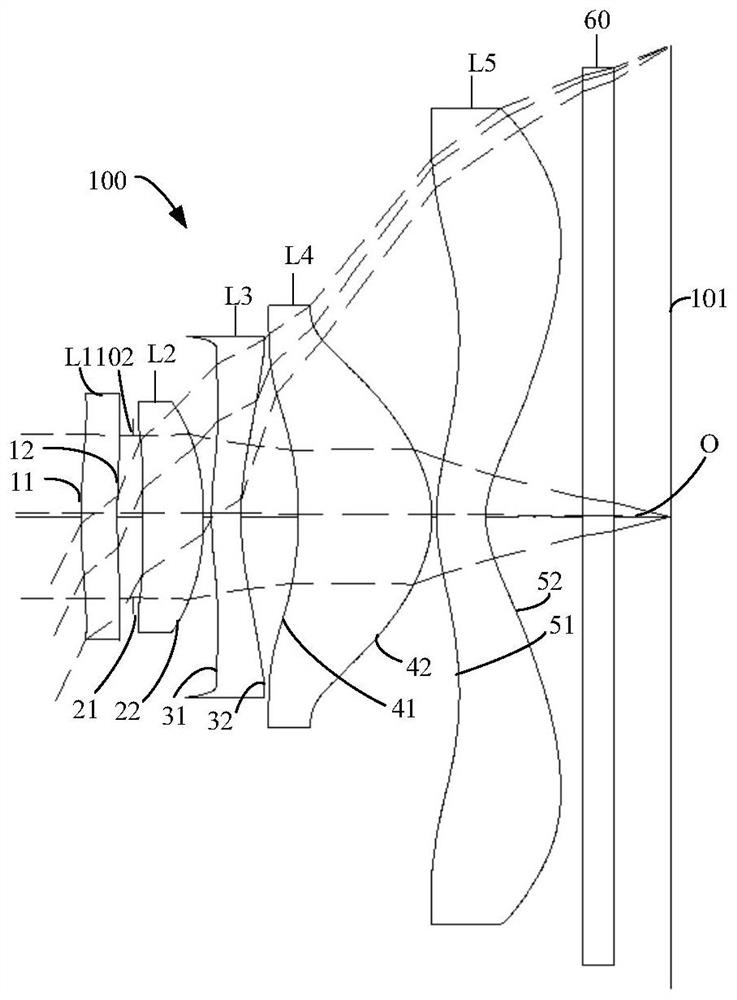
[0116] The structural diagram of the optical lens 100 disclosed in the second embodiment of the present application is as follows image 3 As shown, the optical lens 100 includes a first lens L1, a diaphragm 102, a second lens L2, a third lens L3, a fourth lens L4, a fifth lens L5, an infrared Filter 60. Wherein, the first lens L1 has positive refractive power, the second lens L2 has positive refractive power, the third lens L3 has negative refractive power, the fourth lens L4 has positive refractive power, and the fifth lens L5 has negative refractive power.

[0117] Further, the object side 11 of the first lens L1 is convex at the near optical axis O, and the image side 12 of the first lens L1 is concave at the near optical axis O; the object side 21 and image side 22 of the second lens L2 are at The near optical axis O is concave and convex respectively; the object side 31 and image side 32 of the third lens L3 are respectively convex and concave at the near optical axis O...

no. 3 example

[0127] The structural diagram of the optical lens 100 disclosed in the third embodiment of the present application is as follows Figure 5As shown, the optical lens 100 includes a first lens L1, a second lens L2, a diaphragm 102, and a third lens L3 that are sequentially arranged along the optical axis O from the object side to the image side. The first lens L1 , the diaphragm 102 , the second lens L2 , the third lens L3 , the fourth lens L4 , the fifth lens L5 , and the infrared filter 60 are arranged in sequence on the image side. Wherein, the first lens L1 has positive refractive power, the second lens L2 has positive refractive power, the third lens L3 has negative refractive power, the fourth lens L4 has positive refractive power, and the fifth lens L5 has negative refractive power.

[0128] Further, the object side 11 of the first lens L1 is convex at the near optical axis O, and the image side 12 of the first lens L1 is concave at the near optical axis O; the object sid...


PUM


Abstract

The invention discloses an optical lens, a camera module and electronic equipment. The optical lens comprises a first lens, a second lens, a third lens, a fourth lens and a fifth lens which are sequentially arranged along an optical axis from an object side to an image side, the first lens has positive focal power, and the object side surface and the image side surface of the first lens are a convex surface and a concave surface near the optical axis respectively; the second lens has positive focal power, the image side surface of the second lens is a convex surface at the light inlet axis, and the third lens has focal power; the fourth lens has focal power, and the object side surface of the fourth lens is a convex surface near the optical axis; and the fifth lens has focal power, the object side surface and the image side surface of the fifth lens are respectively a convex surface and a concave surface near the optical axis, and the optical lens meets the relational expression: 1.2 < SD11/SD21 < 1.6. According to the optical lens, the camera module and the electronic equipment, the ultra-wide-angle imaging effect can be realized on the basis of considering the miniaturization and light and thin design of the optical lens.

Description

technical field [0001] The present application relates to the technical field of optical imaging, in particular to an optical lens, a camera module and electronic equipment. Background technique [0002] In recent years, various electronic devices equipped with imaging lenses (including digital cameras, smart phones, notebook computers, tablet computers, etc.) are rapidly developing and popularizing. Among them, the improvement of the portability of electronic equipment puts forward higher requirements for the thickness of the camera lens. At the same time, the use of chips with a large image surface has become an inevitable trend. The support leads to the decline of imaging image quality and deterioration of manufacturability; especially for ultra-wide-angle camera lenses, because conventional ultra-wide-angle camera lenses use a quasi-symmetrical structure in the middle of the aperture, it is difficult to fully miniaturize the ultra-wide-angle camera lens, so the improveme...

Claims


Application Information

Patent Timeline
Patent Type & Authority Applications(China)
IPC IPC(8): G02B13/00G02B13/18
CPCG02B13/0045G02B13/18G03B30/00
Inventor 党绪文刘彬彬李明
Owner JIANGXI JINGCHAO OPTICAL CO LTD
Why Eureka
Try Eureka