Terrestrial magnetism correction apparatus

A correction device and geomagnetic technology, which can be used in image duplicators, image reproducers using cathode camera tubes, etc., can solve problems such as inconvenience

Inactive Publication Date: 2004-02-25
SAMSUNG ELECTRONICS CO LTD
View PDF0 Cites 1 Cited by
  • Summary
  • Abstract
  • Description
  • Claims
  • Application Information

AI Technical Summary

Problems solved by technology

Therefore, this prior ar

Method used


Image

  • Terrestrial magnetism correction apparatus
  • Terrestrial magnetism correction apparatus
  • Terrestrial magnetism correction apparatus

Examples


Embodiment Construction

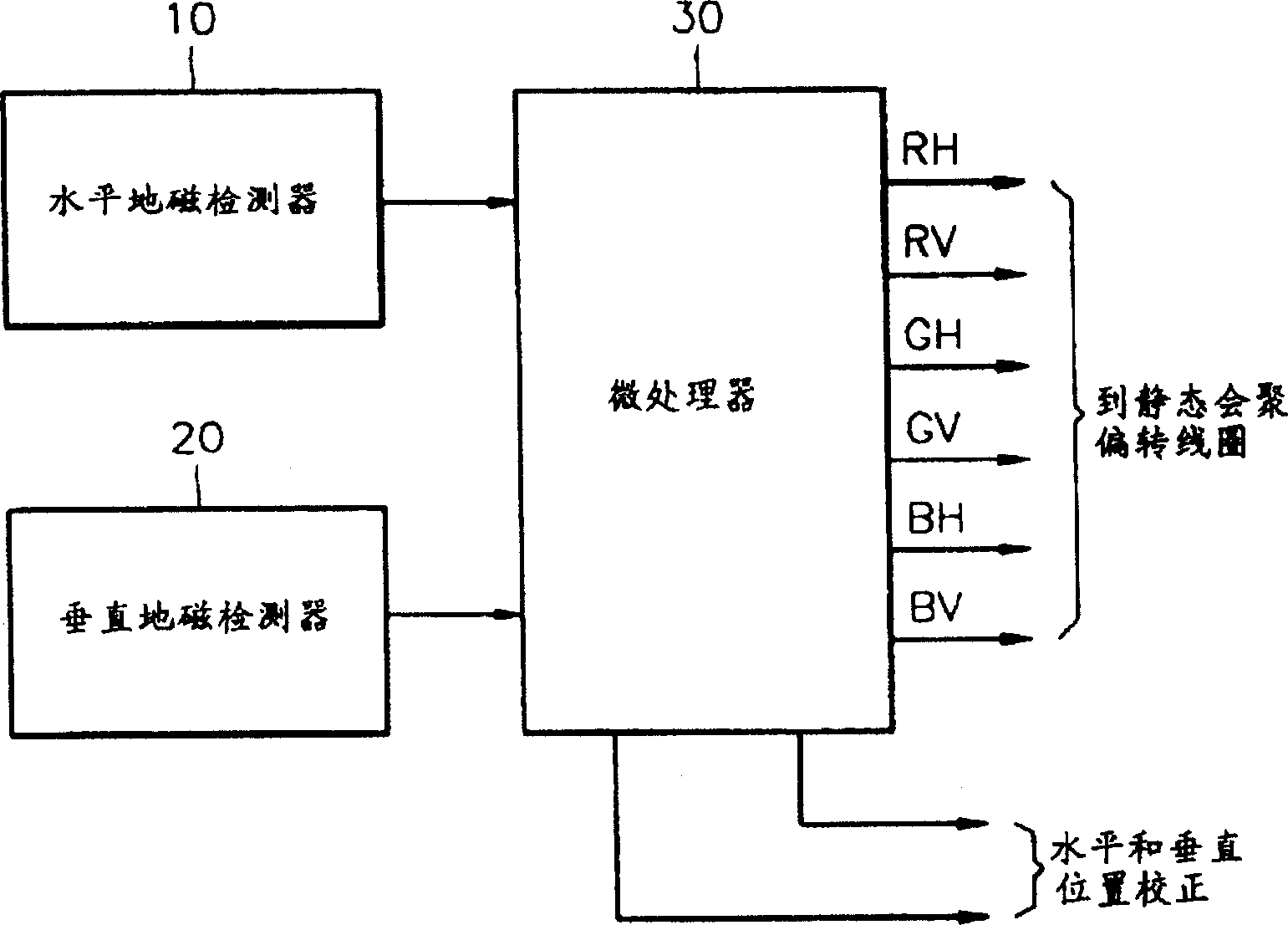
[0013] see figure 1 , the geomagnetic correction device according to the present invention includes a horizontal geomagnetic detector 10 for detecting horizontal geomagnetism, a vertical geomagnetic detector 20 for detecting vertical geomagnetism, and is used to calculate a correction value according to the detected horizontal or vertical geomagnetism, and Microprocessor 30 that automatically compensates for the detected geomagnetism.

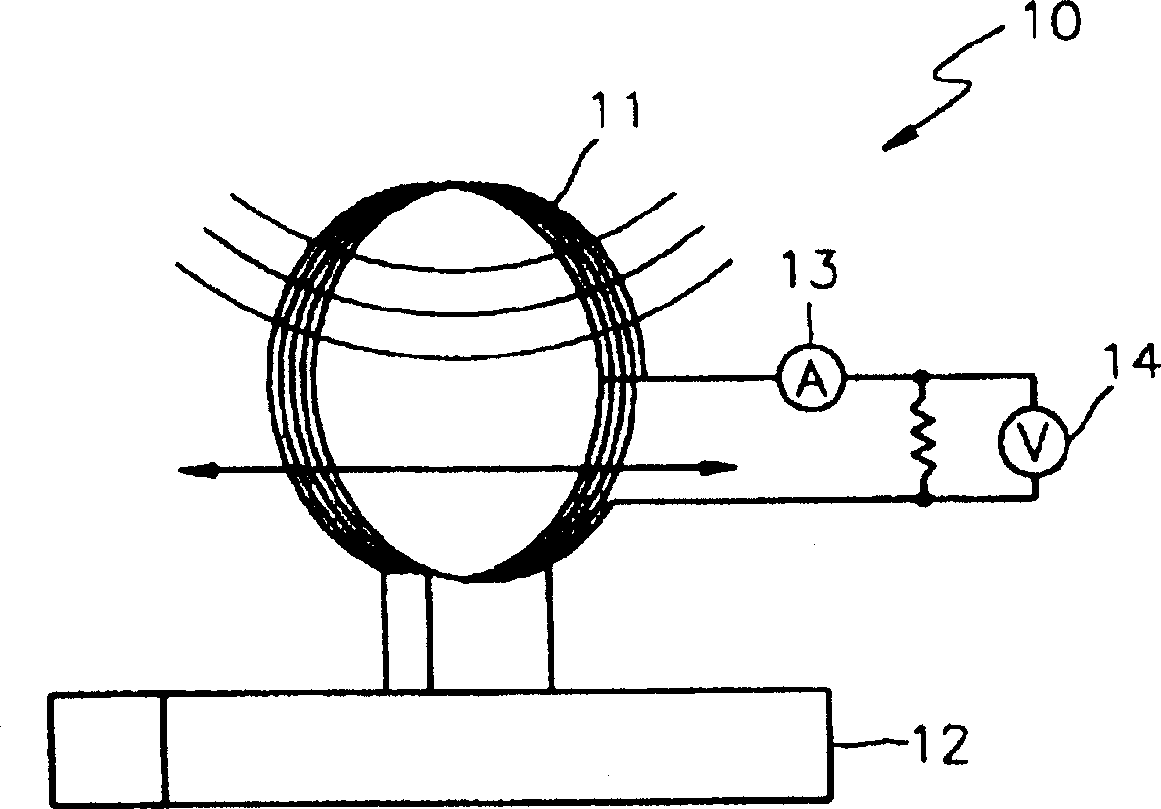
[0014] see Figure 2A , the horizontal geomagnetic detector 10 includes a geomagnetic coil 11, a coil fixing device 12 that is used to fix the geomagnetic coil 11 to a predetermined position on the CRT, and when the CRT moves in a horizontal direction, is used to detect the current generated by the geomagnetic coil 11 and Voltage current and voltage detectors 13 and 14 .

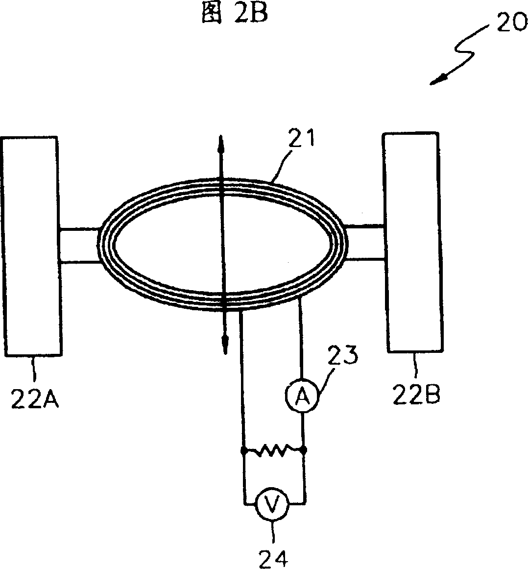
[0015] 2B, the vertical geomagnetic detector 20 includes a geomagnetic coil 21, and is used to fix the geomagnetic coil 21 to coil fixtures 22A and 22B at predetermined pos...


PUM


Abstract

A terrestrial magnetism correction apparatus for automatic correcting converging error caused by terrestrial magnetism determined by installation direction of cathode ray tube (CRT), including horizontally magnetism detector for detecting horizontally magnetism; a vertically magnetism detector for detecting vertically magnetism; and a microprocessor for automatic magnetism correcting, wherein coils are arranged on predetermined position of CRT, terrestrial magnetism acts on coils and generates measurable current or voltage when coils moved horizontally and vertically, calculating corrected value determined by detected terrestrial magnetism to automatic compensate terrestrial magnetism, conveniently correcting accurately without need of hand correcting when spectators looking screen.

Description

technical field [0001] The present invention relates to a geomagnetic correction device, and more particularly, to a geomagnetic correction device capable of improving convergence by automatically compensating for the influence of geomagnetism depending on the installation direction of a television set. Background technique [0002] In cathode ray tubes (CRTs) widely used as display devices or television receivers, when red (R), green (G) and blue (B) light beams are deflected due to geomagnetism, image quality and focus are degraded. Therefore, in order to prevent incorrect deflection of the R, G and B beams, convergence adjustment is performed so as to focus the image on one point. Convergence adjustment can be performed using static convergence adjustment to focus the image on the center of the screen, or dynamic convergence adjustment to focus the image on the periphery of the screen. [0003] Since the relative orientation of the earth's magnetic field varies with resp...

Claims


Application Information

Patent Timeline
IPC IPC(8): H04N9/29
CPCH04N9/29
Inventor 李甲根
Owner SAMSUNG ELECTRONICS CO LTD
Why Eureka
Try Eureka