Intelligent cable receiving device

It is a technology of a leader and a cable, which is applied in the field of a smart cable leader, which can solve the problems of manual operation and waste of time by the staff, and achieve the effect of increasing stability

Pending Publication Date: 2022-02-08
YANTAI POWER SUPPLY COMPANY OF STATE GRID SHANDONG ELECTRIC POWER
View PDF10 Cites 3 Cited by
  • Summary
  • Abstract
  • Description
  • Claims
  • Application Information

AI Technical Summary

Problems solved by technology

[0004] The purpose of the present invention is to solve the shortcomings of the existing cable rewinding, cutting and weighing operations that require manual operations by staff and waste time, and the proposed cable intelligent applicator

Method used


Image

  • Intelligent cable receiving device
  • Intelligent cable receiving device
  • Intelligent cable receiving device

Examples


Embodiment 1

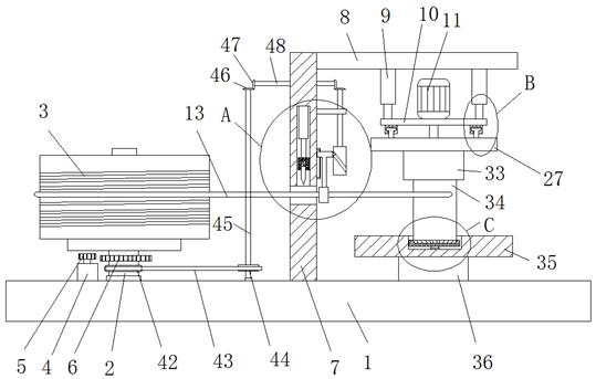
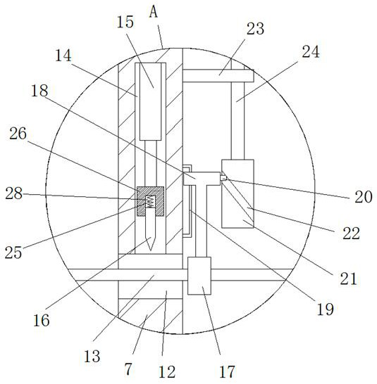
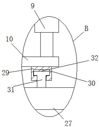
[0027] refer to Figure 1-5 , the intelligent cable receiving device, including a base plate 1, a cable reel placement mechanism is arranged on the top of the base plate 1, a cable reel 3 is placed on the top of the cable reel placement mechanism, and a cable 13 is wound on the cable reel 3, and the base plate 1 is equipped with a vertical plate 7 and a weighing device 36, the vertical plate 7 is provided with a wire hole 12, the top inner wall of the wire hole 12 is provided with a receiving groove 14, and a cutting mechanism is arranged in the receiving groove 14, and the cable 13 and the wire Holes 12 are movably connected, and the cutting mechanism is adapted to the cable 13. A horizontal plate 8 is installed on the top of the vertical plate 7, and a lifting mechanism is installed on the bottom of the horizontal plate 8. A circular plate 10 is installed on the lifting mechanism, and the top of the circular plate 10 Rotating motor 11 is installed, and rotating disc 27 is in...

Embodiment 2

[0035] refer to Figure 1-5 , the intelligent cable receiving device, including a base plate 1, a cable reel placement mechanism is arranged on the top of the base plate 1, a cable reel 3 is placed on the top of the cable reel placement mechanism, and a cable 13 is wound on the cable reel 3, and the base plate 1 is equipped with a vertical plate 7 and a weighing device 36, the vertical plate 7 is provided with a wire hole 12, the top inner wall of the wire hole 12 is provided with a receiving groove 14, and a cutting mechanism is arranged in the receiving groove 14, and the cable 13 and the wire Holes 12 are movably connected, and the cutting mechanism is adapted to the cable 13. A horizontal plate 8 is installed on the top of the vertical plate 7, and a lifting mechanism is installed on the bottom of the horizontal plate 8. A circular plate 10 is installed on the lifting mechanism, and the top of the circular plate 10 Rotating motor 11 is installed, and rotating disc 27 is in...


PUM


Abstract

The invention belongs to the technical field of cable receiving, in particular to an intelligent cable receiving device, and aims to solve the problems that existing operations such as cable winding, cutting and weighing need to be manually operated by workers, and time is wasted, the following scheme is provided, the intelligent cable receiving device comprises a bottom plate, and a cable disc placing mechanism is arranged at the top of the bottom plate; a cable disc is placed on the top of the cable disc placing mechanism, a cable is wound on the cable disc, a vertical plate and a weighing device are installed on the top of the bottom plate, a cable hole is formed in the vertical plate, a containing groove is formed in the inner wall of the top of the cable hole, a cutting mechanism is arranged in the containing groove, the cable is movably connected with the cable hole, and the cutting mechanism is matched with the cable. A transverse plate is installed at the top of the vertical plate, a lifting mechanism is installed at the bottom of the transverse plate, and a circular plate is installed on the lifting mechanism. The cable receiving device is convenient to operate, cables can be automatically wound, cut, weighed and the like, manual operation of workers is not needed, and time is saved.

Description

technical field [0001] The invention relates to the technical field of cable harnesses, in particular to an intelligent cable harnesser. Background technique [0002] Cable is a general term for items such as optical cables and cables. There are many uses of cables, mainly used for multiple functions such as control installation, connection equipment, power transmission, etc. It is a common and indispensable thing in daily life. Cables need to be reeled, cut and weighed before use. The quality of the cable, the weighing function is to detect whether the cable is qualified. [0003] Existing operations such as winding, cutting and weighing of cables require manual operations by staff, which wastes time. Contents of the invention [0004] The purpose of the present invention is to solve the shortcomings of the existing cable rewinding, cutting and weighing operations that require manual operations by staff and waste time, and propose an intelligent cable retrieving device....

Claims


Application Information

Patent Timeline
Patent Type & Authority Applications(China)
IPC IPC(8): B65H54/54B65H54/44B65H54/70B65H57/14B65H67/04B21F11/00
CPCB65H54/54B65H54/44B65H54/70B65H57/14B65H67/0411B21F11/00B65H2701/34
Inventor 张明超肖峰李明吕重阳李秉格韩振兴
Owner YANTAI POWER SUPPLY COMPANY OF STATE GRID SHANDONG ELECTRIC POWER
Why Eureka
Try Eureka