Double-effect combined inverted-cone-shaped graphite falling film evaporator

A technology of falling film evaporator and inverted conical shape, which is applied in the field of double-effect combined inverted conical graphite falling film evaporator, which can solve the problems of cloth film thickness adjustment, evaporator heat exchange tube processing problems, scaling and other problems, and achieve convenient Effects of regulation, good cycle performance, efficient cleaning

Active Publication Date: 2020-07-31
南通熠能精细石墨科技有限公司
View PDF16 Cites 4 Cited by
  • Summary
  • Abstract
  • Description
  • Claims
  • Application Information

AI Technical Summary

Problems solved by technology

When the material liquid cannot evenly wet the inner surface of all the heating tubes, the surface of the lack of liquid or the lack of liquid may be scaled due to evaporation, and the scaled surface in turn blocks the flow of the liquid film, thereby reducing the heat transfer in the adjacent area. Conditions deteriorate further
[0005] Due to the different viscosities and flow properties of different feed liquids, it is necessary to consider the influence of the thickness of the film on the uniform film distribution effect when distributing the film to ensure that it flows smoothly, is not easy to clog and the film is evenly distributed, but the existing graphite reduces the It is difficult for the film evaporator to adjust the thickness of the film, that is, it is necessary to use different types of falling film evaporators for different types of feed liquids. In addition, the treatment of the fouling of the feed liquid in the heat exchange tube of the evaporator is still a big problem

Method used


Image

  • Double-effect combined inverted-cone-shaped graphite falling film evaporator
  • Double-effect combined inverted-cone-shaped graphite falling film evaporator
  • Double-effect combined inverted-cone-shaped graphite falling film evaporator

Examples


Embodiment

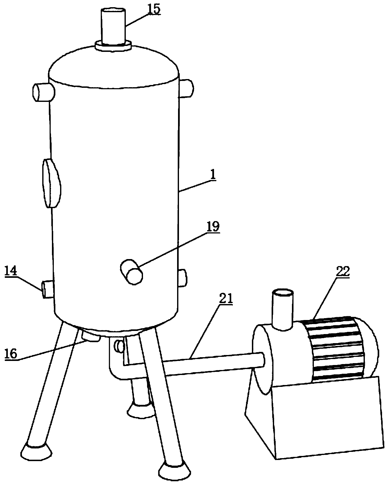
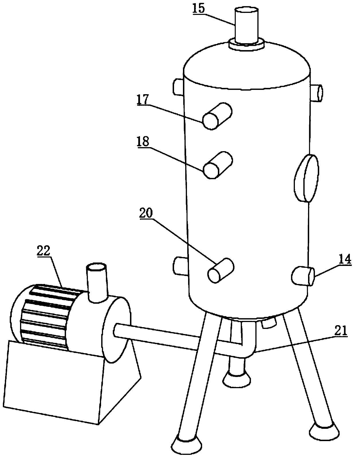
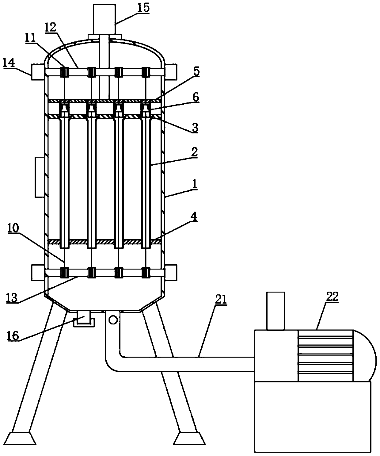
[0043] see figure 1 , a double-effect combined inverted conical graphite falling film evaporator, including a shell 1, see image 3 , the inside of the shell 1 is fixedly connected with the upper plate 3 and the lower plate 4, the upper plate 3 is located on the upper side of the lower plate 4, the inside of the shell 1 is provided with a plurality of uniformly distributed heat exchange tubes 2, and the heat exchange tubes 2 The upper and lower ends respectively pass through the upper plate 3 and the lower plate 4 and are fixedly connected to the inside. The upper plate 3 and the lower plate 4 are used to fix the heat exchange tubes 2. The upper side of the upper plate 3 is provided with a movable plate 5, and the side of the movable plate 5 The wall is slidingly connected with the inner wall of the housing 1, and the top of the housing 1 is fixedly connected with an electric push rod 15, and the telescopic end of the electric push rod 15 runs through the top of the housing 1 ...


PUM


Abstract

The invention discloses a double-effect combined inverted-cone-shaped graphite falling film evaporator, and belongs to the field of falling film evaporators. The double-effect combined inverted-cone-shaped graphite falling film evaporator comprises a shell; an upper disc and a lower disc are fixedly connected in the interior of the shell; the upper disc is positioned on the upper side of the lowerdisc; a plurality of uniformly distributed heat exchange tubes are arranged in the shell; and the upper ends and the lower ends of the heat exchange tubes penetrate the upper disc and the lower disccorrespondingly and are fixedly connected with the interiors of the upper disc and the lower disc. The cloth film thickness can be reasonably set according to the characteristics of viscosity, flowingproperty and the like of the feed liquid; the feed liquid can smoothly flow along the inner walls of the heat exchange tubes in a film shape; uniform film distribution of the feed liquid in the heatexchange tubes is ensured; compared with a conventional falling film evaporator, the provided falling film evaporator has better adaptability; the problem that feed liquid scales in the heat exchangetubes are difficult to clean is solved by arranging line connection type cleaning columns in a liquid separation groove, multiple heat exchange tubes can be efficiently and synchronously cleaned, andthe falling film evaporator can be well used for multiple times in cycle.

Description

technical field [0001] The invention relates to the field of falling film evaporators, in particular to a double-effect combined inverted conical graphite falling film evaporator. Background technique [0002] Falling film evaporation is to add the feed liquid from the upper tube box of the heating chamber of the falling film evaporator, and distribute it evenly into each heat exchange tube through the liquid distribution and film forming device. flow up and down. Due to the good anti-corrosion performance of graphite materials, it is widely used in some high-corrosion industries and fields. Graphite falling film evaporators use steam heating and evaporation. The parts of the equipment that are in contact with corrosive media are made of impregnated graphite, which is chemically stable. Good performance, high evaporation efficiency. [0003] The feed liquid distributor is a key part of the falling film evaporator. The feed liquid enters the feed liquid distributor from the...

Claims


Application Information

Patent Timeline
Patent Type & Authority Applications(China)
IPC IPC(8): B01D1/22B01D1/30
CPCB01D1/22B01D1/30
Inventor 吕佳
Owner 南通熠能精细石墨科技有限公司
Why Eureka
Try Eureka