Solar receiving device and heat absorber

A technology of receiving device and solar energy, applied in the field of solar energy, can solve the problems of reducing power generation time, easily generating thermal stress, damaging the heat collector, etc., achieving sufficient and uniform heat exchange, improving energy density, and increasing the effect of flow path

Active Publication Date: 2017-06-30
深圳中科能投能源有限公司
View PDF5 Cites 3 Cited by
  • Summary
  • Abstract
  • Description
  • Claims
  • Application Information

AI Technical Summary

Problems solved by technology

Because only one side of the heat collector absorbs heat, when the heat exchange efficiency with the power generation working fluid passing through the heat collector is not high, thermal stress is easily generated, thus damaging the heat collector
In response to this problem, the industry generally solves it by increasing the area of ​​the heat collector, but this solution increases the construction cost on the one hand, and reduces the unit energy density of the heat collector on the other hand, which reduces the efficiency of solar thermal power generation. As a result, it is impossible to work at full power in summer, and when the sun is insufficient in winter, it cannot reach the normal operating temperature of the driving steam turbine, which reduces the power generation time

Method used


Image

  • Solar receiving device and heat absorber
  • Solar receiving device and heat absorber
  • Solar receiving device and heat absorber

Examples


Embodiment 1

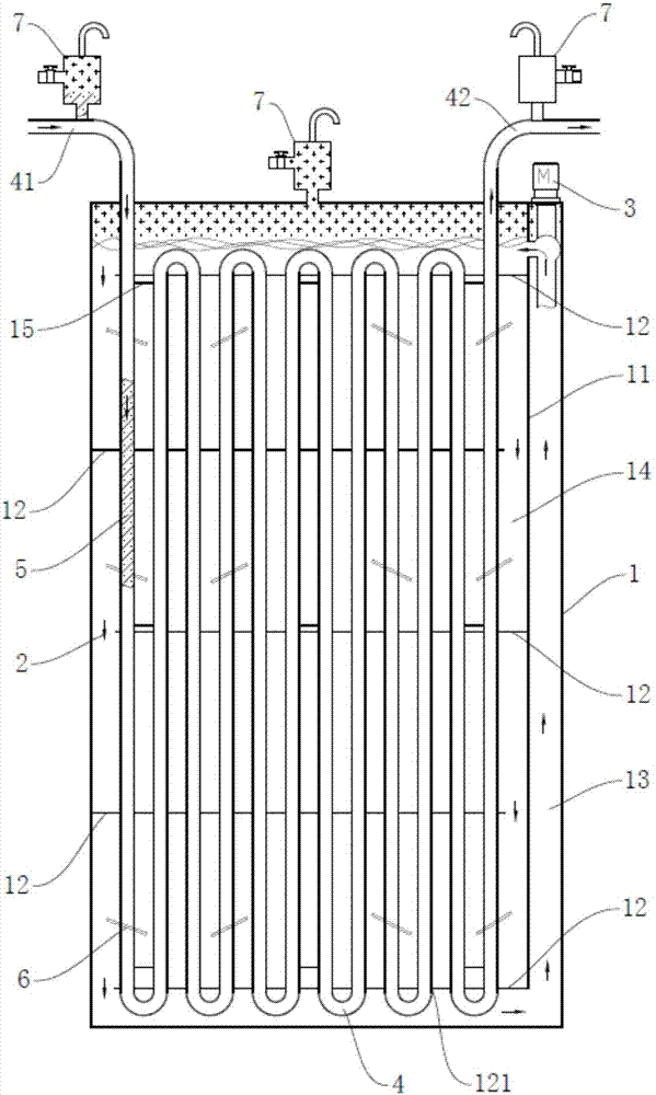
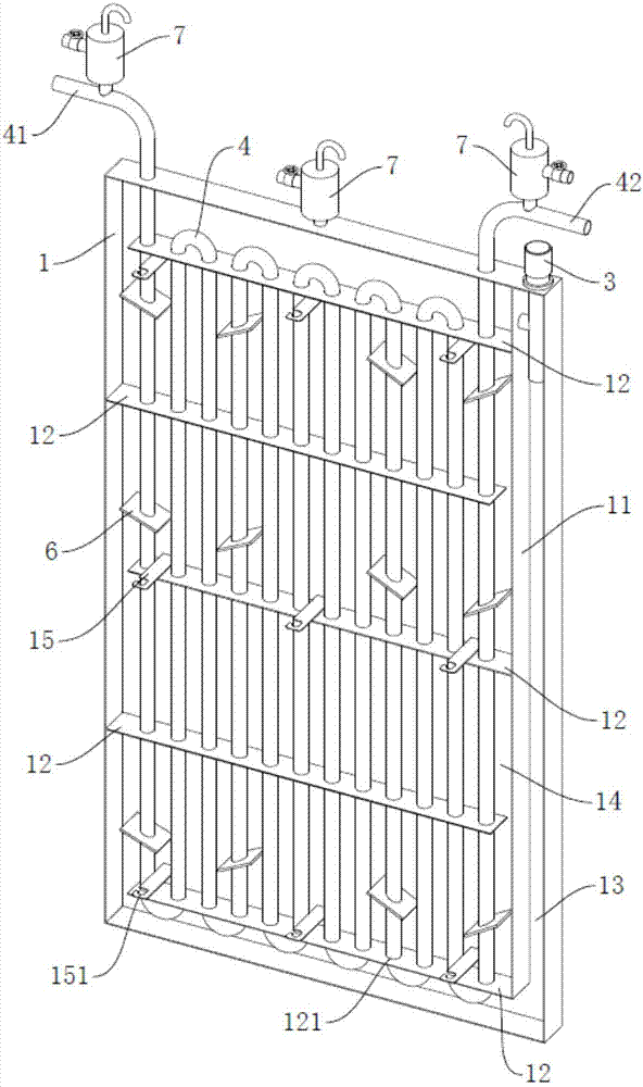
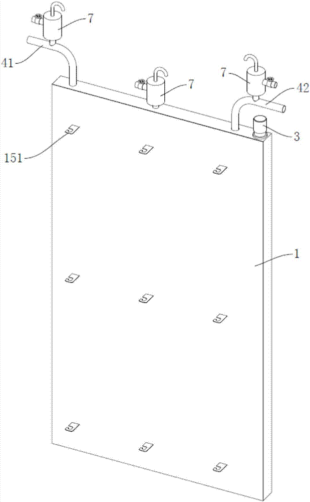
[0028] The solar receiving device includes a first container 1 , a first working medium 2 is arranged in the first container 1 , and a driving device 3 for driving the first working medium 2 is connected to the first container 1 . Preferably, the driving device 3 is a pump. The first container 1 is also provided with a second container 4, the second container 4 is provided with a second working fluid 5, the second container 4 is provided with an inlet 41 and an outlet 42 of the second working fluid 5, the first working fluid 2 The thermal conductivity is greater than the thermal conductivity of the second working fluid 5, and the first container 1 is also provided with a main side plate 11 for forming the return flow channel 13 of the first working fluid 2 and a plurality of flow guides for forming the first working fluid 2 The guide plate 12 of the channel 14 and the driving device 3 are arranged at one end of the return channel 13 , and both ends of the return channel 13 are...

Embodiment 2

[0040] This embodiment is based on Embodiment 1, and the difference between this embodiment and Embodiment 1 is: the first working medium 2 is a lead-tin alloy, and the second working medium 5 is air.

[0041] This embodiment also provides a solar heat absorber, which includes a tower body, a heat collector is arranged on the top of the tower body, and the heat collector includes at least one of the above-mentioned solar energy receiving devices. Preferably, the heat collector includes six of the above solar receiving devices.

[0042] The heat of sunlight heats the lead-tin alloy in the above-mentioned solar receiver to 1000 degrees, and the lead-tin alloy evenly heats the pipeline soaked in it, and heats the air flowing in the pipe to about 990 degrees to drive the heat engine to generate electricity.


PUM


Abstract

The invention discloses a solar receiving device and a heat absorber. The solar receiving device comprises a first container which contains a first working medium inside. The first container is connected with a driving device used for driving the first working medium to flow. A second container is further arranged in the first container, and a second working medium is arranged in the second container. The second container is provided with an inlet and an outlet for the second working medium, and the heat conductivity of the first working medium is larger than that of the second working medium. A main side plate used for forming a backflow channel of the first working medium and a plurality of flow guide plates used for forming a flow guide channel of the first working medium are further arranged in the first container, and the driving device is arranged at one end of the backflow channel. The second container is immersed in the first working medium in the first container, when the driving device drives the first working medium in the first container to flow, heat of the first working medium can be uniformly transferred to the second working medium in the second container, the energy density of the solar receiving device is effectively improved, and the thermal stress of the solar receiving device is reduced.

Description

technical field [0001] The invention relates to the technical field of solar energy, in particular to a solar energy receiving device and a heat absorber. Background technique [0002] At present, non-renewable energy sources are facing two major problems. One is the depletion of energy sources, and the other is the emission of a large amount of carbon dioxide, which causes air pollution and the greenhouse effect. Therefore, people urgently need an alternative energy source, and solar energy, as an inexhaustible, clean, non-polluting, high-efficiency and low-cost energy source, has attracted more and more attention. [0003] Solar thermal power generation is divided into trough line focusing system, dish system and tower system, and the tower system has gradually become the mainstream of solar thermal power generation system due to its high efficiency and low cost. The principle of the tower system is to use multiple heliostats that independently track the sun to focus the ...

Claims


Application Information

Patent Timeline
Patent Type & Authority Applications(China)
IPC IPC(8): F24J2/30F24J2/26F24J2/46F24J2/51F24J2/48F24S10/30F24S10/75
CPCF24S10/30F24S10/755F24S40/00F24S70/10F24S70/12F24S80/00F24S80/60Y02E10/44
Inventor 孙海翔赵晓东滕广平夏越段谦君
Owner 深圳中科能投能源有限公司
Why Eureka
Try Eureka