
Lifting platform

A lifting table and lifting frame technology, applied in the field of lifting table, can solve the problems of inability to meet the installation of the center pin of various models, difficulty in meeting the accuracy requirements of the center pin, and low degree of freedom in the installation of the center pin, so as to meet the needs of multi-degree-of-freedom adjustment. , The effect of high installation stability and improved installation efficiency

Pending Publication Date: 2022-02-08
苏州中车轨道交通车辆有限公司
View PDF6 Cites 2 Cited by
  • Summary
  • Abstract
  • Description
  • Claims
  • Application Information

AI Technical Summary

Problems solved by technology

However, in the process of realizing the inventive technical solution in the embodiment of the application, the inventor of the present application found that the above-mentioned technology still has the following technical problems: a kind of auxiliary positioning device and method for the traction center pin of the EMU disclosed in the CN110435687A patent, it needs to rely on the lower part The position of the guide rail is adjusted on the track. The freedom of center pin installation is not high, and it is difficult to meet the accuracy requirements of center pin installation and alignment. The lifting device only considers the adjustment requirements of one degree of freedom, which cannot meet the center pin installation and alignment requirements. Adjustment requirements in the XY plane, center pin installation accuracy is not high, can not meet the center pin installation of various models

Method used


Image

  • Lifting platform
  • Lifting platform
  • Lifting platform

Examples


Embodiment Construction

[0031] The present invention will be further described below in conjunction with the accompanying drawings and specific embodiments, so that those skilled in the art can better understand the present invention and implement it, but the examples given are not intended to limit the present invention.

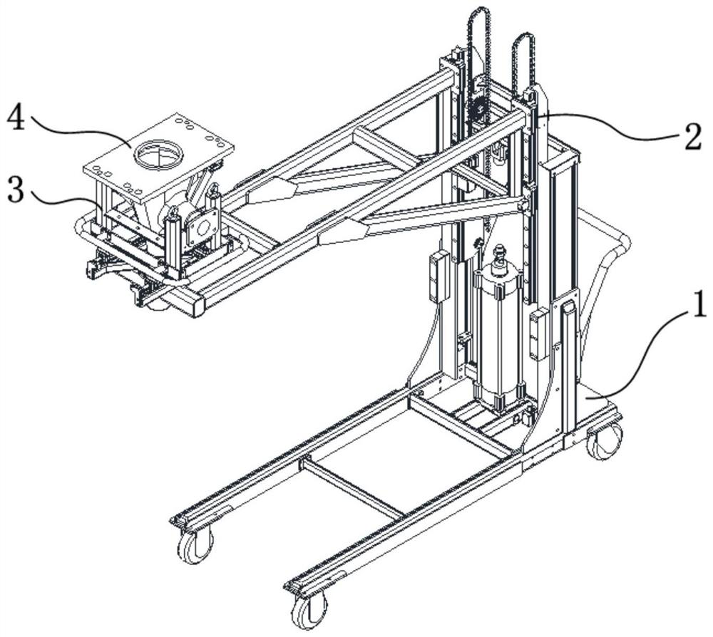
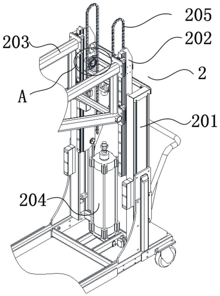
[0032] refer to Figure 1 to Figure 6 As shown, the present invention discloses a lifting platform, including: a machine base 1 , a moving module 2 and a loading assembly 3 .

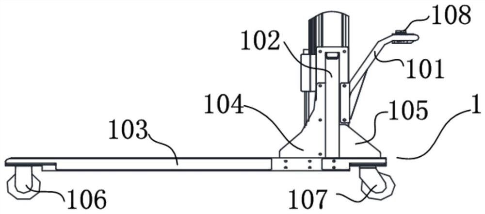
[0033] Above-mentioned machine base 1 comprises walking push rod 101, two symmetrical columns 102, main body frame 103, left rib 104, right rib 105, directional wheel 106, band brake universal wheel 107 and lift control button 108. Wherein, the walking push rod 101 is connected by bolts between two symmetrical columns 102 . The two symmetrical uprights 102 are welded and fixed to the main body frame 103 , and the left rib 104 and the right rib 105 are connected to the two symmetrical uprights 102 by bolts....


PUM


Abstract

The invention relates to a lifting platform which comprises a machine base, a first moving module arranged on the machine base, a second moving module, and a carrying assembly; the first moving module comprises a first driving source and a first lifting frame which is vertically arranged; the first lifting frame is connected with the machine base, and the first driving source drives the first lifting frame to reciprocate up and down in the vertical direction; the second moving module comprises a second driving source and a second lifting frame which is horizontally arranged; one end of the second lifting frame is arranged on the first lifting frame in a sliding mode, and the second driving source drives the second lifting frame to move up and down on the first lifting frame in a reciprocating mode; the carrying assembly is used for placing a to-be-mounted center pin; a rotating shaft is installed at the other end of the second lifting frame, and the carrying assembly is rotationally arranged on the rotating shaft. The center pin can be effectively lifted to a vehicle bottom mounting position, the multi-degree-of-freedom adjusting requirement can be met, it is guaranteed that the required positioning precision can be achieved during center pin mounting, operation is easy, and mounting stability is high.

Description

technical field [0001] The invention relates to the technical field of subway vehicle parts installation, in particular to a lifting platform. Background technique [0002] In the general assembly production process of subway vehicles, the upper body of the vehicle is generally produced first, and the connection between the upper and lower bodies of the vehicle is completed after the upper body is produced and assembled. The center pin of the subway is an important part installed on the underframe of the upper body of the vehicle and installed before the upper and lower bodies are connected. The center pin of subway vehicles is generally a casting, which is heavy and irregular in shape. It is labor-intensive to install through manual handling, easy to fall off, and poses a safety hazard. A special tooling needs to be designed for the installation of the center pin of subway vehicles. [0003] In the patent with the Chinese patent publication number CN110435687A, an auxiliar...

Claims


Application Information

Patent Timeline
Patent Type & Authority Applications(China)
IPC IPC(8): B66F7/04B66F7/28
CPCB66F7/04B66F7/28
Inventor 李海林闫伟范恒境邵勇黄旭葛俊
Owner 苏州中车轨道交通车辆有限公司
Learn More