Filling device in filling machine

A filling device and filling machine technology, applied in bottling machines, synchronous devices, packaging, etc., can solve the problems of time-consuming and labor-intensive disassembly and installation of filling valves, energy-intensive filling equipment, and regular replacement, so as to achieve saving Reduce energy consumption, shorten filling time, and facilitate replacement

Active Publication Date: 2022-02-08
JIANGSU NEWAMSTAR PACKAGING MACHINERY
View PDF8 Cites 0 Cited by
  • Summary
  • Abstract
  • Description
  • Claims
  • Application Information

AI Technical Summary

Problems solved by technology

The technical problems of the current filling device are: 1. The return flow is large during the filling process; 2. The sealing elements in the filling valve, such as sealing rings, and elastic elements such as springs need to be replaced regularly
The disassembly and installation of the filling valve is time-consuming and laborious, and the maintenance of each filling equipment requires a lot of energy

Method used


Image

  • Filling device in filling machine
  • Filling device in filling machine
  • Filling device in filling machine

Examples


Embodiment Construction

[0022] The present invention will be further described in detail below in conjunction with the accompanying drawings and preferred embodiments.

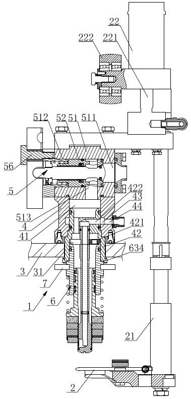
[0023] Such as figure 1 , figure 2 As shown, the filling device in the filling machine includes: a filling valve 1, and a bottle clamp 2 is arranged below the filling valve 1.

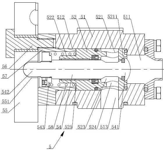
[0024]The structure of the filling valve 1 includes: a valve seat 4 fixedly arranged on the installation frame 3 , and an upper valve cavity 41 is arranged in the valve seat 4 . The top of the valve seat 4 is provided with a liquid inlet control mechanism 5, the liquid inlet control mechanism 5 includes: a liquid inlet valve seat 51 fixedly connected with the valve seat 4, and the two ends of the liquid inlet valve seat 51 are respectively provided with a liquid inlet 511 and a valve The seat installation through hole 512, the valve block 52 extends into the liquid inlet valve seat 51 through the valve seat installation through hole 512, and the outer wall...


PUM


Abstract

The invention discloses a filling device in a filling machine, which comprises a filling valve, a bottle clamp is arranged below the filling valve, the structure of the filling valve comprises a valve seat fixedly arranged on a mounting rack, an upper valve cavity is arranged in the valve seat, a liquid inlet control mechanism is arranged at the top of the valve seat, and the bottom of the valve seat is detachably connected with a filling valve body for filling a bottle. The filling valve body comprises a filling valve cavity and a filling valve element, the filling valve cavity is communicated with the upper valve cavity, the filling valve element is hollow to form a backflow channel, and the backflow channel is communicated with a valve seat backflow hole channel in the valve seat. The filling device has the advantages that firstly, a liquid inlet control mechanism is arranged and can control the filling amount of materials, the surplus filling amount is reduced as much as possible on the premise that the filling requirement is met, and therefore the backflow amount is reduced, and the filling efficiency is improved; and secondly, the liquid inlet control mechanism is detachable, and the filling valve body can be integrally mounted and dismounted, so that the mounting and the maintenance of the filling valve are greatly facilitated.

Description

technical field [0001] The invention relates to the technical field of liquid filling equipment, in particular to a filling machine. Background technique [0002] The filling device in the filling machine mainly includes a filling valve and a bottle clamp. The bottle clamp is arranged below the filling valve. The bottle clamp is driven by a cylinder, and the bottle clamp can move vertically up and down under the drive of the cylinder. There are usually dozens of groups of filling devices on the rotary filling machine. The technical problems existing in the current filling device are: 1. The return flow is large during the filling process; 2. The sealing elements in the filling valve, such as sealing rings, and elastic elements such as springs need to be replaced regularly. The disassembly and installation of the filling valve is time-consuming and labor-intensive, and the maintenance of each filling equipment requires a lot of energy. Contents of the invention [0003] T...

Claims


Application Information

Patent Timeline
Patent Type & Authority Applications(China)
IPC IPC(8): B67C3/26B67C3/28B67C3/24B67C7/00
CPCB67C3/2637B67C3/26B67C3/28B67C3/242B67C7/004
Inventor 沈军张虎邵凤丹
Owner JIANGSU NEWAMSTAR PACKAGING MACHINERY
Why Eureka
Try Eureka