Reinforcing structure and reinforcing method for partially cutting off connecting beam damaged by earthquake
A technology of reinforcing structure and partial removal, applied in earthquake resistance, building components, building structure, etc., can solve the problems of construction difficulty and construction volume trouble of workers, and achieve the effect of easy maintenance, increase connection life, and avoid loosening.
- Summary
- Abstract
- Description
- Claims
- Application Information
AI Technical Summary
Problems solved by technology
Method used
Image
Examples
Embodiment 1
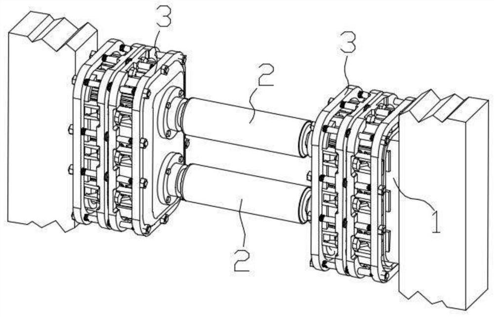
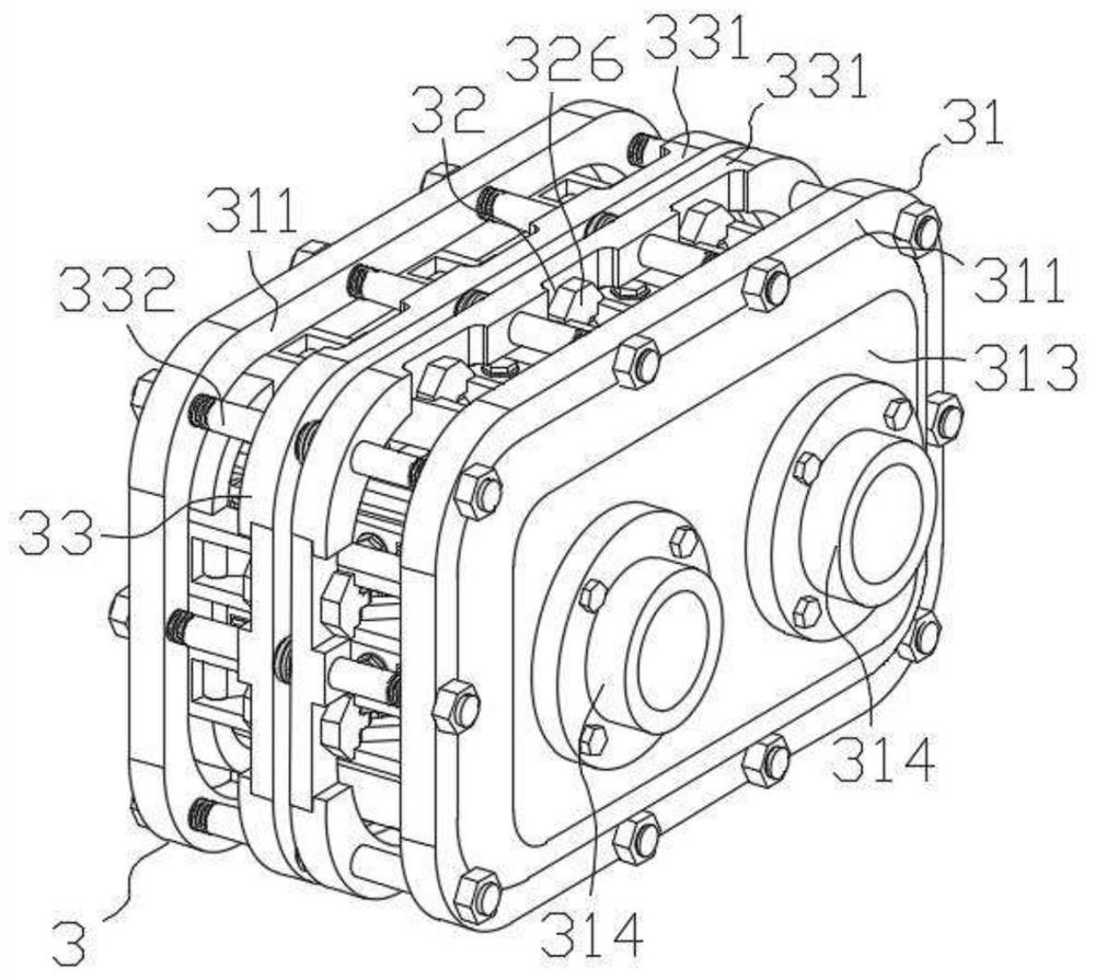
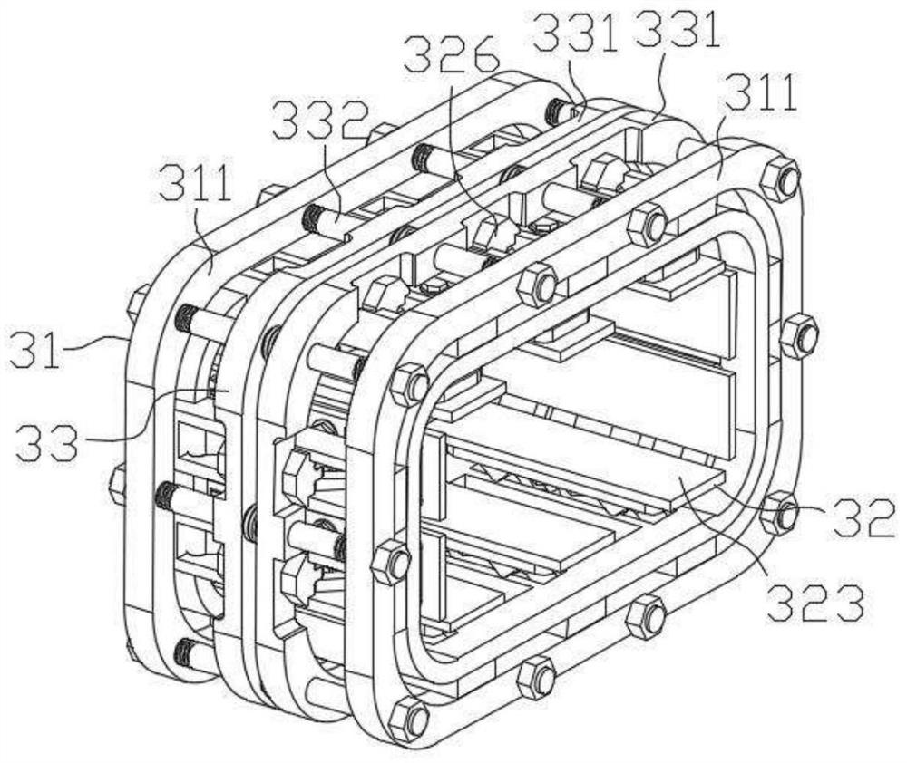
[0050] Such as figure 2 , 3 As shown, the reinforcement structure 3 includes three parts: a frame main body 31, a transmission assembly 32 and a fastening assembly 33, specifically:
[0051] 1) Frame body 31
[0052] Such as figure 2 , 3 , 4, the frame body 31 includes two sets of ring brackets 311 arranged front and back and multiple groups of chute pieces 312 equidistantly arranged between the two sets of ring brackets 311. The front surface of the frame body 31 is also provided with a 2 connected connecting plate body 313, the connecting plate body 313 is provided with a ball hinge support 314 connected with the damper 2, the frame main body 31 is prepared by integral molding or welding molding,
[0053] 2) transmission assembly 32
[0054] Such as figure 2 , 3 , 5, the transmission assembly 32 includes two sets of V-shaped connecting rods 321 symmetrically arranged on both sides of the chute member 312, the bottom connecting piece 322 and the anti-slip gasket 323...
Embodiment 2
[0069] This embodiment is basically the same as Embodiment 1, and its reinforcement method is the same as Embodiment 1. The difference is that the damper is selected, such as Figure 8 As shown, the damper used in this embodiment is a variable damper 4: the variable damper 4 is arranged between the remaining sections 1 of the connecting beam at both ends, and the balls at both ends of the connecting plate 313 on the corresponding side are respectively The hinge support 314 is connected,
[0070] Such as Figure 9 , 10 As shown, the variable damper 4 includes an upper support 41, a lower support 42, and a piston 43 and a piston rod 44 that are arranged on the upper support 41 and cooperate with the lower support 42. The piston 43 connects with the upper support through the piston rod 44. The inner top surface of 41 is connected, and the piston 43 includes a piston outer shell 431 and a piston inner shell 432,
[0071] Such as Figure 11 As shown, the piston housing 431 is a...
Embodiment 3
[0079] Such as Figure 13 As shown, a method for partial excision and reinforcement of earthquake-damaged coupling beams includes the following steps:
[0080] Step 1: Partial removal of earthquake-damaged coupling beams
[0081] Cut off the energy-dissipating section in the middle part of the earthquake-damaged coupling beam, the cut-off middle part is 600mm, and keep the remaining section 1 of the coupling beam without energy-consuming sections at both ends;
[0082] Step 2: Reinforcement of the remaining section 1 of the coupling beam
[0083] The end of the residual section 1 of the coupling beam is pre-embedded with the connecting steel plate 5 used to connect with the damper 2. The connecting steel plate 5 is selected from the commercially available Q460 steel plate, and the cracks at the end of the residual section 1 of the coupling beam are repaired with commercially available high ductility concrete treatment, and the remaining section 1 of the coupling beam is rein...
PUM
 Abstract
Description
Claims
Application Information
 - R&D
- Intellectual Property
- Life Sciences
- Materials
- Tech Scout
- Unparalleled Data Quality
- Higher Quality Content
- 60% Fewer Hallucinations
Browse by: Latest US Patents, China's latest patents, Technical Efficacy Thesaurus, Application Domain, Technology Topic, Popular Technical Reports.
© 2025 PatSnap. All rights reserved.Legal|Privacy policy|Modern Slavery Act Transparency Statement|Sitemap|About US| Contact US: help@patsnap.com


