Fan

A fan and fan motor technology, applied in the direction of ventilation system, space heating and ventilation, heating and ventilation hood/cover, etc., can solve the problems of large air volume in the lower part of the nozzle blowing, lower air quality, and small air volume in the upper part, etc., to improve the user Experience and expand the effect of usage scenarios

Pending Publication Date: 2022-02-08
浙江弩牌电器有限公司
View PDF0 Cites 0 Cited by
  • Summary
  • Abstract
  • Description
  • Claims
  • Application Information

AI Technical Summary

Problems solved by technology

[0004] 1. The position of inhaled air is low, it is easy to inhale the dust on the ground or the countertop, thus reducing the air quality and shortening the service life of the air purifier in the fan
[0005] 2. The filter of the traditional bladeless fan is set at the lower part. Take the usage scenario of the fan on the ground as an example. Every time the filter is replaced, the user needs to disassemble the casing and bend down to take out the old filter, and bend down again Changing to a new filter, the user experience is not good, especially for the elderly to replace the filter, there are hidden dangers in use
[00

Method used


Image

  • Fan
  • Fan
  • Fan

Examples


Example Embodiment

[0048] Example embodiments will now be described more fully with reference to the accompanying drawings. However, example embodiments can be embodied in various forms and should not be construed as limited to the embodiments set forth herein. Rather, these embodiments are provided so that this disclosure will be thorough and complete, and will fully convey the concept of example embodiments to those skilled in the art. The same reference numerals in the drawings denote the same or similar structures, and thus their repeated descriptions will be omitted.

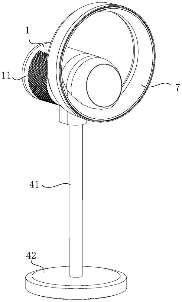
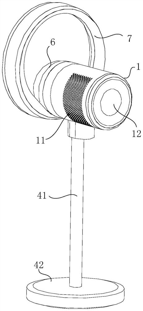
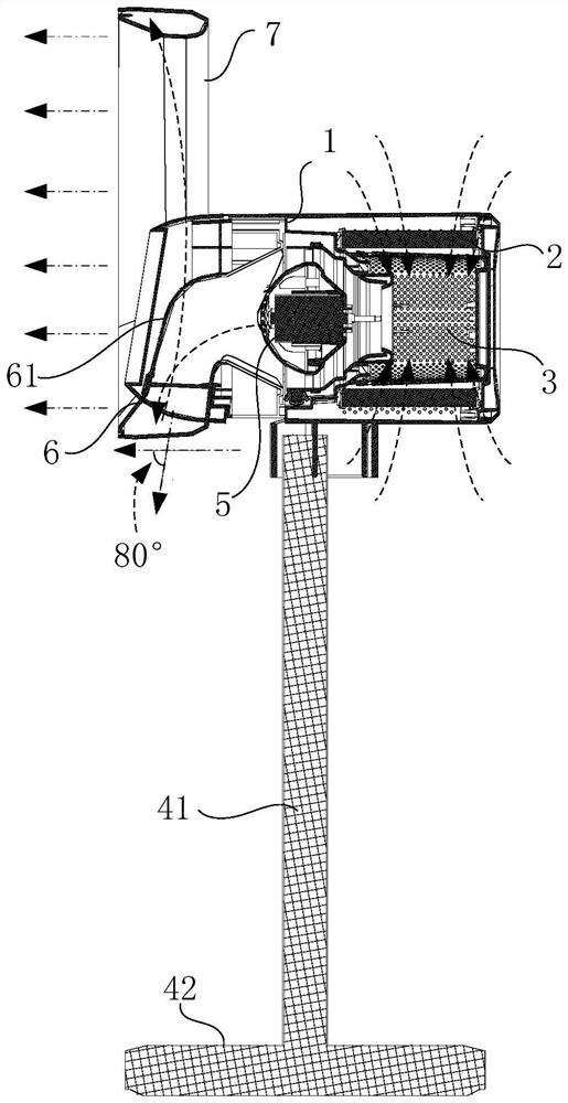
[0049] figure 1 It is a perspective view of the fan of the present invention from a first perspective. figure 2 It is a perspective view of the fan of the present invention from a second perspective. image 3 It is a side sectional view of the fan of the present invention. like Figures 1 to 3 As shown, the fan of the present invention includes: an integral part 1 , a support member 41 , a base 42 and a nozzle 7 . The ...


PUM


Abstract

The invention provides a fan. The fan comprises: a body part, which comprises an air inlet, an air outlet and a fan motor assembly, wherein the fan motor assembly comprising a horizontal motor for generating an air flow passing through the body part; a supporting piece, which is used for supporting the body part; and a nozzle, which is connected with the body part based on the air outlet direction of the horizontal motor, and is used for receiving the air flow from the body part, dispersing the air flow to each air outlet along the interior of the nozzle and spraying the air flow. According to the invention, an air suction position can be lifted, indoor surface air is prevented from entering the fan, wind power can be concentrated to be emitted at a high position, a traditional vertical fan is completely replaced, a use scene is expanded, and user experience is improved.

Description

technical field [0001] The present invention relates to the field of air conditioning and, in particular, to fans. Background technique [0002] Most of the existing bladeless fans are in the mode of low suction and upward blowing. The vertical motor at the bottom of the bladeless fan sucks in air from the bottom, and the vertical air flow is generated by the vertical motor, which is delivered to the air above the vertical motor. After the nozzle, the air flow is guided to the horizontal direction by the inside of the nozzle and sprayed. [0003] There are following technical problems in this structure: [0004] 1. The air intake position is low, and it is easy to inhale the dust on the ground or the countertop, thereby reducing the air quality and shortening the service life of the air purifier in the fan. [0005] 2. The filter of the traditional bladeless fan is set at the lower part. Take the usage scenario of the fan on the ground as an example. Every time the filter ...

Claims


Application Information

Patent Timeline
IPC IPC(8): F04D25/08F04D29/70F04D29/40F04D29/60F04D27/00F04F5/46F24F8/108F24F13/20F24F13/28F24F7/003F24F7/007
CPCF04D25/08F04D25/06F04D29/703F04D29/403F04D29/601F04D27/002F04F5/46F24F8/108F24F13/20F24F13/28F24F7/003F24F7/007
Inventor 应辉周小锋
Owner 浙江弩牌电器有限公司
Why Eureka
Try Eureka