
Backlight module and display device

A backlight module and display area technology, applied in optics, nonlinear optics, instruments, etc., can solve the problems affecting the optical quality of the backlight module, abnormal display device display, abnormal optical quality, etc. Offset, reduce the effect of light leakage

Pending Publication Date: 2022-02-08
XIAMEN TIANMA MICRO ELECTRONICS
View PDF0 Cites 2 Cited by
  • Summary
  • Abstract
  • Description
  • Claims
  • Application Information

AI Technical Summary

Problems solved by technology

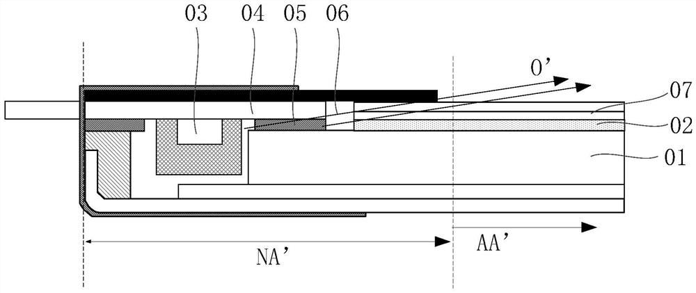
However, this countermeasure is for the current front-set narrow-frame backlight module, because the frame size will be further reduced by about 0.4mm compared with the conventional front-set backlight module, and the light incident distance of the backlight module is continuously compressed, and the backlight module When the group is assembled, it is necessary to reserve the matching space 06 of the optical film material. In this case, the diffusion black bars cannot be reserved, and the distance between the light source LED 03 and the display area AA' is shorter, and the brightness near the light source LED 03 is higher, so that The light output direction of the light guide plate 01 close to the light source LED 03 cannot be effectively shielded, resulting in abnormal optical quality and fireflies in the backlight module
[0003] In addition, after removing the diffused black stripes, the light O' emitted by the light source LED 03 can also pass through the lamp glue 05, and optical scattering occurs on the prism section of the enhancement sheet 07, aggravating the phenomenon of fireflies at the border of the display and affecting the optical performance of the backlight module. Taste, which in turn leads to display abnormalities in the display device using the backlight module

Method used


Image

  • Backlight module and display device
  • Backlight module and display device
  • Backlight module and display device

Examples


Embodiment Construction

[0034] The present invention will be further described in detail below in conjunction with the accompanying drawings and embodiments. It should be understood that the specific embodiments described here are only used to explain the present invention, but not to limit the present invention. In addition, it should be noted that, for the convenience of description, only some structures related to the present invention are shown in the drawings but not all structures.

[0035] It should be clear that the described embodiments are only some of the embodiments of the present invention, not all of them. Based on the embodiments of the present invention, all other embodiments obtained by persons of ordinary skill in the art without creative efforts fall within the protection scope of the present invention.

[0036] Techniques, methods and devices known to those of ordinary skill in the relevant art may not be discussed in detail, but where appropriate, such techniques, methods and de...


PUM


Abstract

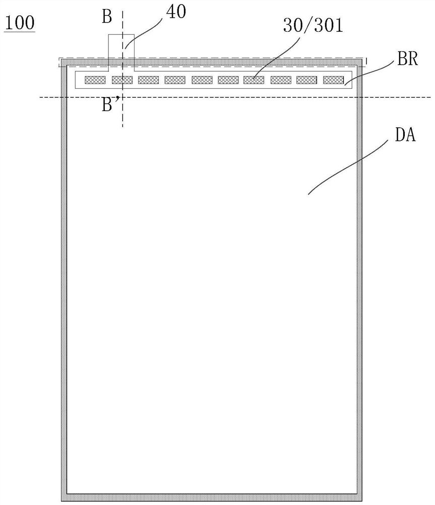
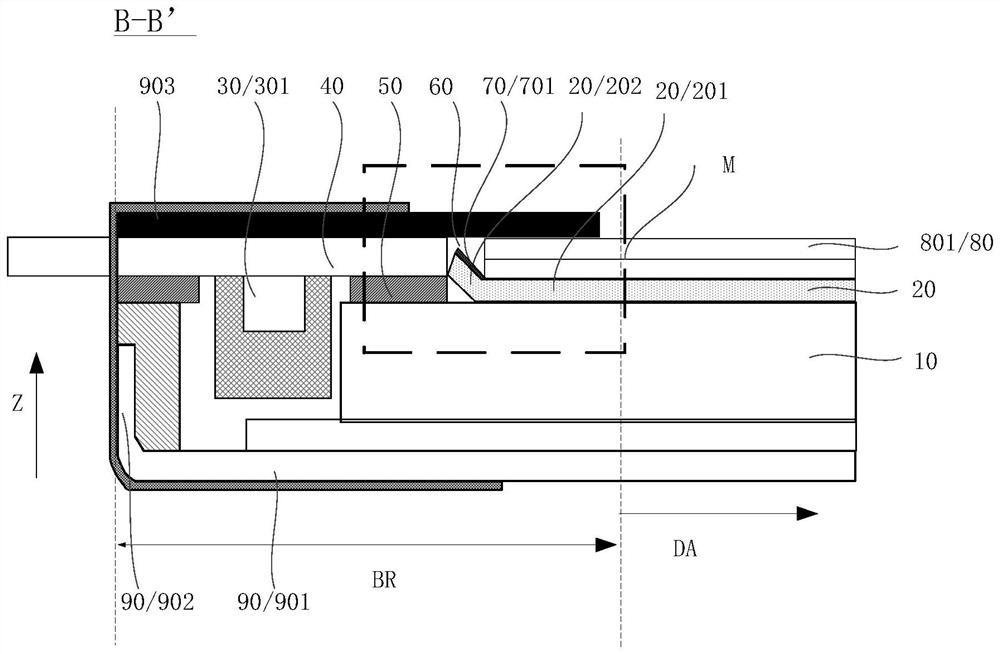
An embodiment of the invention provides a backlight module and a display device. The backlight module has a display area and a frame area surrounding the display area, and comprises: a light-emitting device and a circuit board electrically connected with the light-emitting device, wherein the circuit board is located on the side, facing the light-emitting direction of the backlight module, of the light-emitting device; a light guide plate located on the side, close to the display area, of the light-emitting device; lamp glue positioned between the light guide plate and the circuit board; a diffusion sheet which is located on the side, facing the light emitting direction of the backlight module, of the light guide plate and comprises a body part and a bent part connected with the body part, wherein the bent part is located on the side, close to the light-emitting device, of the body part, and the bent part is bent towards the side, away from the light guide plate, of the body part relative to the body part; and a shading film which comprises a first branch part, wherein the first branch part at least partially covers the bending part. According to the backlight module provided by the embodiment of the invention, the phenomena of light leakage and firefly of the backlight module can be improved, and the phenomena of light leakage or bright line of the display device caused by deviation of the diffusion sheet during assembly of the backlight module can be improved.

Description

technical field [0001] The invention relates to the field of display technology, in particular to a backlight module and a display device. Background technique [0002] In the existing positive side-type backlight module, such as figure 1 as shown, figure 1 Shown is a schematic diagram of a partial structure of the backlight module provided in the prior art; since the thickness of the light guide plate 01 is smaller than the thickness of the light source LED 03, the light emitting angle of the light source LED 03 is about 120 degrees, therefore, when the light source LED 03 When the light emitted by 03 does not enter the light guide plate 01, side light leakage will occur; although the flexible circuit board 04 above the light source LED 03 is bonded to the upper surface of the light-emitting side of the light guide plate 01 through the adhesive layer 05, and is equipped with a diffusion black strip (not shown) Out) design can control the light leakage phenomenon within th...

Claims


Application Information

Patent Timeline
Patent Type & Authority Applications(China)
IPC IPC(8): G02F1/13357G02F1/1335
CPCG02F1/133615G02F1/133504G02F1/133512
Inventor 黄阿海
Owner XIAMEN TIANMA MICRO ELECTRONICS
Learn More