Continuous measurement method for crack length

A technology of crack length and measurement method, used in image data processing, instrument, character and pattern recognition, etc., can solve the cumbersome operation method of flexibility method, the test personnel cannot be liberated from mechanical operation, and the potential method is susceptible to current and The impact of the environment, etc., to achieve the effect of improving the measurement efficiency

Pending Publication Date: 2022-02-08
NORTHWESTERN POLYTECHNICAL UNIV
View PDF0 Cites 0 Cited by
  • Summary
  • Abstract
  • Description
  • Claims
  • Application Information

AI Technical Summary

Problems solved by technology

The above three methods of measuring cracks all have different disadvantages: the visual method prevents the testers from being freed from mechanical operations; the potential method is easily affected by current and the environment; the operation method of the flexibility method is too cumbersome

Method used


Image

  • Continuous measurement method for crack length
  • Continuous measurement method for crack length
  • Continuous measurement method for crack length

Examples


Embodiment

[0038] The technical scheme that the present invention solves the problems of the technologies described above is as follows:

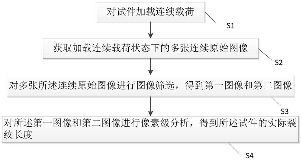
[0039] The invention provides a continuous measuring method of crack length, referring to figure 1 As shown, the continuous measurement method of the crack length includes:

[0040] S1: Continuous load is applied to the specimen;

[0041] S2: Obtain multiple continuous original images under continuous loading state;

[0042] Specifically, the speckle field is prepared on the surface of the test piece first, and then the multiple continuous original images are the captured images of the speckle field on the surface of the test piece. In addition, the operator can estimate the initial acquisition point where continuous original images need to be obtained during the process of loading continuous loads on the specimen, maintain the dynamic loading state, and operate at an operating frequency of 1 Hz. Until then, the operating frequency can be increased...


PUM


Abstract

The invention discloses a continuous measurement method for crack length. The continuous measurement method for the crack length comprises the following steps: S1, loading a continuous load on a test piece; S2, acquiring a plurality of continuous original images in a continuous load loading state; S3, performing image screening on the plurality of continuous original images to obtain a first image and a second image; and S4, carrying out pixel-level analysis on the first image and the second image to obtain the actual crack length of the test piece. According to the continuous measurement method for the crack length provided by the invention, the crack length can be measured by using an optical measurement mechanical method on the premise of not suspending a fatigue test, so the measurement efficiency of the crack length is further improved.

Description

technical field [0001] The invention relates to the technical field of crack measurement, in particular to a continuous measurement method for crack length. Background technique [0002] In practical engineering applications, because the internal structure of metal materials is not uniform, resulting in unbalanced stress transmission, some places inside the material will become stress concentration areas; in addition, due to the requirements of structure and technology, changes in the shape of engineering components will also be Cause stress concentration, such as keyways, horizontal holes, etc. on the drive shaft. At the same time, there are many tiny cracks at the defects inside the material. For the above reasons, the occurrence of fatigue cracks is unavoidable in the processing, manufacturing and use of engineering components. Components often break suddenly due to fatigue damage when the working stress is lower than the strength limit, or even lower than the yield lim...

Claims


Application Information

Patent Timeline
IPC IPC(8): G06T7/00G06V10/74
CPCG06T7/001G06T2207/10016G06T2207/30136G06F18/22
Inventor 殷之平李炎罗洁
Owner NORTHWESTERN POLYTECHNICAL UNIV
Why Eureka
Try Eureka