Valve driving circuit and valve control method for intelligent gas meter
A valve drive circuit, valve control technology, applied in valve details, valve devices, engine components, etc., can solve problems such as increased cost, lack of second-line valves, inconvenient gas meter control, etc., to improve compatibility and improve control efficiency. Effect
- Summary
- Abstract
- Description
- Claims
- Application Information
AI Technical Summary
Problems solved by technology
Method used
Image

Examples
Embodiment 1
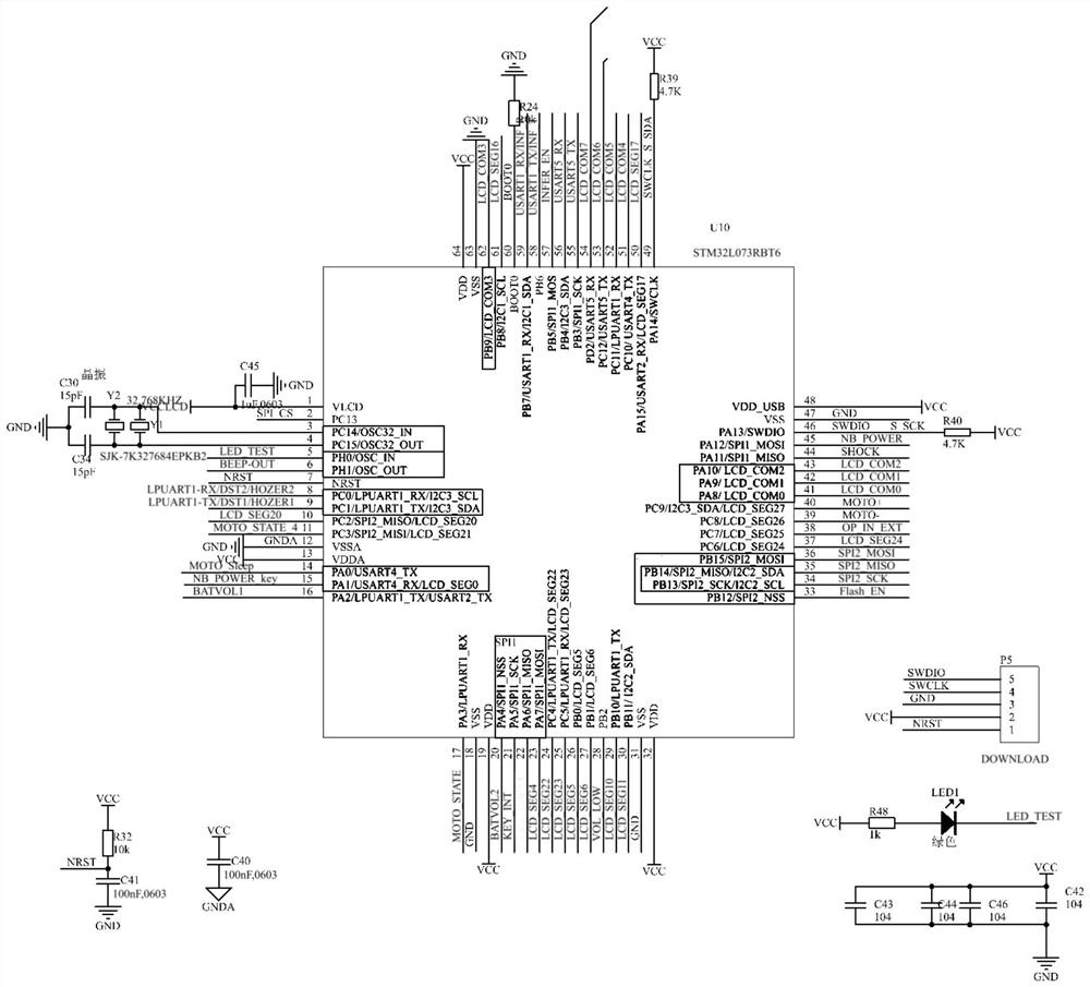
[0047] see Figure 1-3 , this embodiment provides a smart gas meter valve drive circuit, including a gas meter processor U10, a valve drive chip IC1 and a valve interface P8, the valve interface P8 in this embodiment is a four-wire valve interface, it should be noted that the four The wire valve interface can be connected to both the four-wire valve and the second-wire valve. The difference is that the second-wire valve only needs to be connected to the first pin and the first pin.
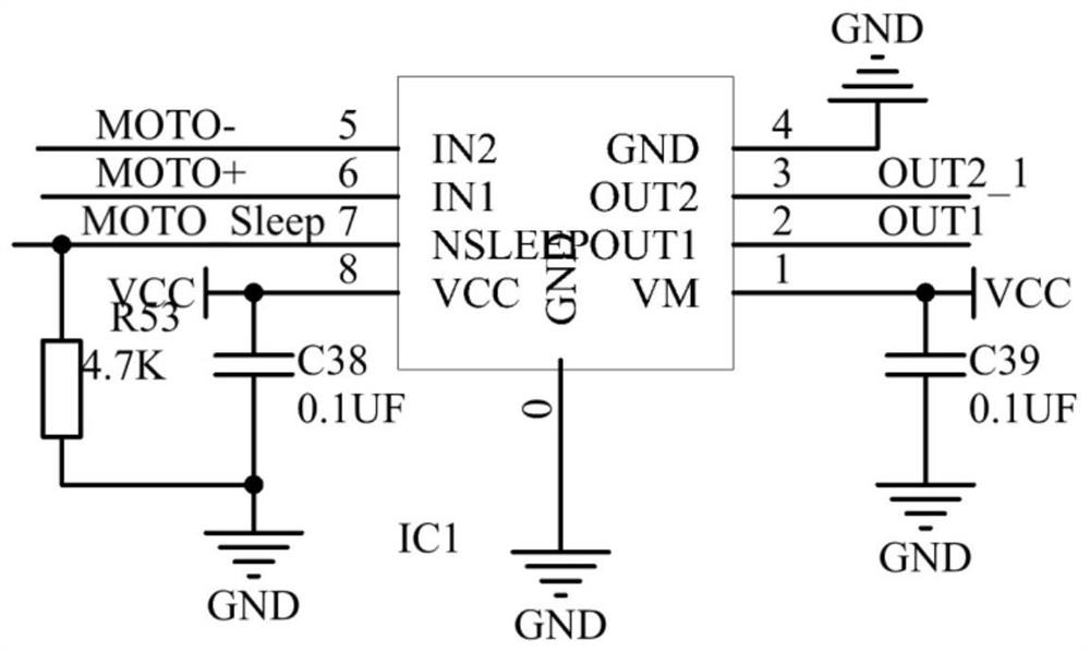
[0048] like figure 2 As shown, the first valve control signal terminal MOTO+ of the gas meter processor U10 is connected to the first input terminal IN1 of the valve driver chip IC1, and the second valve control signal terminal MOTO- of the gas meter processor U10 is connected to the second input terminal IN1 of the valve driver chip IC1. The input terminal IN2, the motor sleep pin NSLEEP of the valve drive chip IC1 is connected to the valve sleep control terminal MOTO_Sleep of the gas meter proce...
Embodiment 2
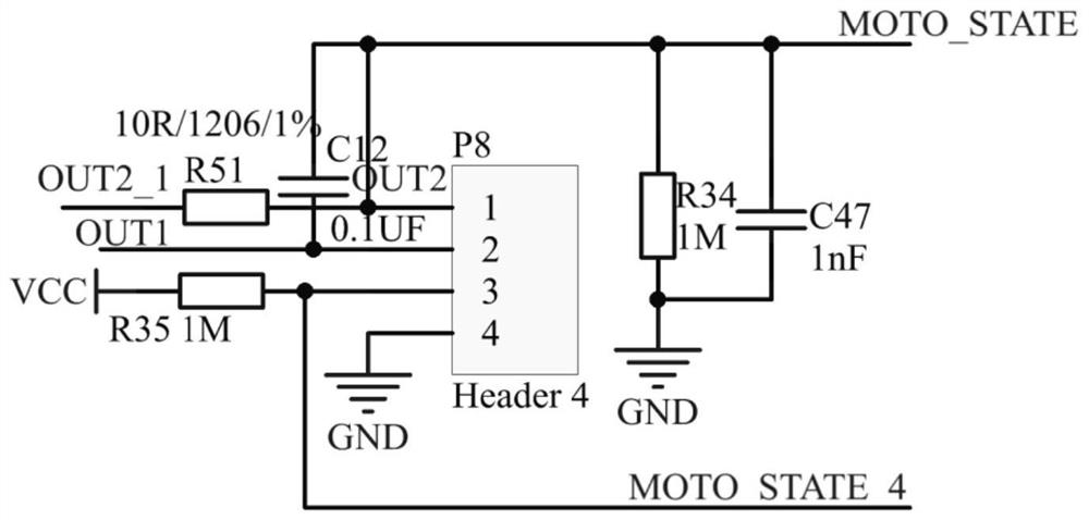
[0066] The design of this embodiment differs from that of Embodiment 1 only in that the valve interface P8 is changed to a second-line valve interface, namely image 3 The connection part between the first pin and the second pin is reserved, and the connection part between the third pin and the fourth pin does not exist.
[0067] The rest of the design is similar to Embodiment 1, see figure 1 and 2 , only the four-wire valve state input terminal MOTO_STATE_4 can be removed in the single-chip microcomputer U10, and will not be repeated here.
[0068] The driving circuit of this embodiment is only applicable to the second-line valve.
[0069] The valve control method of the present embodiment includes:
[0070] For valve opening control steps, see Figure 4 :
[0071] Step S101: the first valve control signal terminal MOTO+ outputs a low level, and the second valve control signal terminal MOTO- outputs a high level;
[0072] At this time, the first output terminal OUT1 of ...
PUM
 Abstract
Description
Claims
Application Information
 - R&D
- Intellectual Property
- Life Sciences
- Materials
- Tech Scout
- Unparalleled Data Quality
- Higher Quality Content
- 60% Fewer Hallucinations
Browse by: Latest US Patents, China's latest patents, Technical Efficacy Thesaurus, Application Domain, Technology Topic, Popular Technical Reports.
© 2025 PatSnap. All rights reserved.Legal|Privacy policy|Modern Slavery Act Transparency Statement|Sitemap|About US| Contact US: help@patsnap.com