Anti-falling remote controller

A remote control and anti-drop technology, which is applied in the field of TV remote control, can solve the problems of internal component damage, easy falling off battery, easy loss of battery, etc., and achieve the effect of preventing loss

Active Publication Date: 2022-02-11
天长市旭日电子配件厂
View PDF6 Cites 3 Cited by
  • Summary
  • Abstract
  • Description
  • Claims
  • Application Information

AI Technical Summary

Problems solved by technology

Beneficial effects of the present invention: the outer side is provided with an anti-fall metal shell, which can have a better anti-fall effect. The remote control in the above patent only uses an anti-aging metal shell. Although the shell is not easy to damage, it is easy to cause damage. Damage to internal components. In addition, the battery cover of the traditional remote control is buckled in the battery slot. It is easy to fall off when it is dropped on the ground, causing the battery to fly out, causing the battery to be easily lost.

Method used


Image

  • Anti-falling remote controller
  • Anti-falling remote controller
  • Anti-falling remote controller

Examples


Embodiment 1

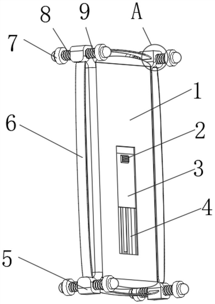
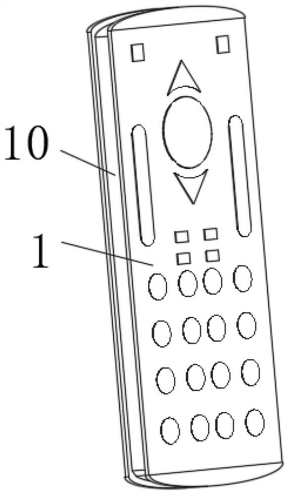
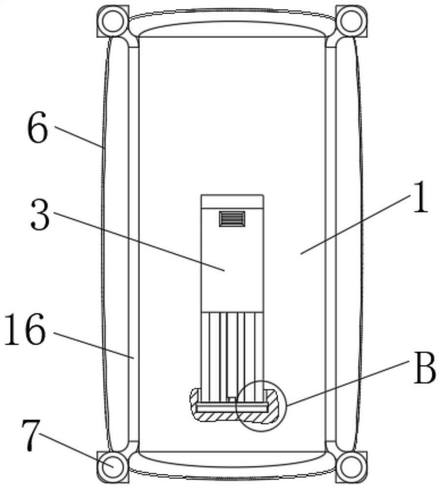
[0038] refer to Figure 1-4 and Figure 6 , the present invention provides an anti-drop remote control, comprising a remote control housing 1, a mounting groove 10 is provided in the middle of the outer periphery of the remote control housing 1, and a sealing sleeve 16 is provided inside the mounting groove 10, and the four corners of the sealing sleeve 16 are uniform. The fixed block 5 is fixedly connected, the top middle part of the fixed block 5 is provided with a through hole 11, the inner middle part of the through hole 11 is fixedly connected with a step 15, and the inner middle part of the through hole 11 is slidably connected with a slide bar 12. The top and bottom ends of the steps are all fixedly connected with the anti-collision head 7, the top of the step 15 is fixedly connected with the second spring 9, the bottom of the step 15 is fixedly connected with the first spring 8, and the middle part of the adjacent side of the fixed block 5 Both are fixedly connected w...

Embodiment 2

[0040] refer to figure 1 , image 3 and Figure 5 The difference between this embodiment and the above-mentioned embodiments is that: the rear end of the remote control housing 1 is provided with a battery slot 4, and the inner wall of the battery slot 4 is provided with a chute 14, and the inner two sides of the chute 14 are slidably connected with a battery cover 3 , the rear end of the battery cover 3 is fixedly connected with a bump 2, the surface of the bump 2 is provided with anti-skid stripes, the bottom end of the chute 14 is fixedly connected with a rubber pad 13, and the middle part of the top of the rubber pad 13 is provided with a gap for installing the battery. Inside the battery slot 4, and move the battery cover 3 to slide inside the chute 14 until the bottom of the battery cover 3 slides into the inside of the gap of the rubber pad 13 to be stuck, which can prevent the battery cover 3 from falling off.

Embodiment 3

[0042] refer to Figure 1-6The difference between this embodiment and the above-mentioned embodiments is that a mounting groove 10 is provided in the middle of the outer circumference of the remote control housing 1, a sealing sleeve 16 is provided inside the mounting groove 10, and a bump 2 is fixedly connected to the rear end of the battery cover 3, The surface of the bump 2 is provided with anti-slip stripes, the bottom end of the chute 14 is fixedly connected with a rubber pad 13, the middle part of the top of the rubber pad 13 is provided with a gap, the inner side of the sealing sleeve 16 is in interference connection with the inner wall of the installation groove 10, and the battery slot The inside of 4 is provided with three battery placement slots, and the sealing sleeve 16 is installed on the outer periphery of the remote control housing 1 so that the liquid will not penetrate from the installation gap, and the battery cover 3 can be effectively locked in the gap in t...


PUM


Abstract

The invention relates to the field of television remote controllers, and discloses an anti-falling remote controller. The anti-falling remote controller comprises a remote controller shell, a mounting groove is formed in the middle of the periphery of the remote controller shell, a sealing sleeve is arranged in the mounting groove, fixing blocks are fixedly connected to the four corners of the sealing sleeve correspondingly, and through holes are formed in the middles of the top ends of the fixing blocks correspondingly. Steps are fixedly connected to the middles of the inner sides of the through holes correspondingly, sliding rods are slidably connected to the middles of the inner sides of the through holes correspondingly, anti-collision heads are fixedly connected to the top ends and the bottom ends of the sliding rods correspondingly, second springs are fixedly connected to the top ends of the steps correspondingly, and first springs are fixedly connected to the bottom ends of the steps correspondingly; metal elastic pieces are fixedly connected to the middles of the adjacent sides of the fixing blocks, and a battery groove is formed in the rear end of the remote controller shell. According to the anti-falling remote controller, the first springs and the second springs are used for buffering, so that the remote controller is not easy to break, and in addition, the battery cover is mounted in a sliding manner and is not easy to fall off.

Description

technical field [0001] The invention relates to the field of television remote controllers, in particular to an anti-drop remote controller. Background technique [0002] The remote control is a device used to remotely control machinery. The modern remote control is mainly composed of integrated circuit boards and buttons used to generate different messages. It is actually a special light-emitting diode. The material is different from ordinary light-emitting diodes, so when a certain voltage is applied across it, it emits infrared light instead of visible light. Patent No. CN205584408U discloses a TV remote control that is anti-pressure and anti-drop, including a remote control body and a remote control panel. Socket, the main body of the remote controller is provided with a lithium battery, the main body of the remote controller is provided with a pressure sensor and an overpressure alarm device, and the anti-drop metal shell is provided with an LED energy-saving lamp swit...

Claims


Application Information

Patent Timeline
Patent Type & Authority Applications(China)
IPC IPC(8): G08C23/04H05K5/02H05K5/06H05K7/14
CPCG08C23/04H05K5/0217H05K5/069H05K7/14Y02E60/10
Inventor 夏立平
Owner 天长市旭日电子配件厂
Why Eureka
Try Eureka